

R602 Wood Wall Framing — 2025 California Residential Code
California Residential Code (Title 24, Part 2.5) · 2025 edition · updated 2026-10-19 · California
CBSC: official editions, supplements and errata
Italicized text is a California amendment to the model code, as printed in the official publication.
Cite as: 2025 California Residential Code (Title 24, Part 2.5) § R602 · Effective January 1, 2026 · Official source: Building Standards Commission
R602.1 General.¶
Wood and wood-based products used for load-supporting purposes shall conform to the applicable provisions of this section.
R602.1.1 Sawn lumber. Sawn lumber shall be identified by a grade mark of an accredited lumber grading or inspection agency and have design values certified by an accreditation body that complies with DOC PS 20. In lieu of a grade mark, a certification of inspection issued by a lumber grading or inspection agency meeting the requirements of this section shall be accepted.
Note: See Section R301.1.1.1 for limited-density owner- built rural dwellings.
R602.1.2 End-jointed lumber. Approved end-jointed lumber identified by a grade mark conforming to Section R602.1 shall be permitted to be used interchangeably with solid-sawn members of the same species and grade. End-jointed lumber used in an assembly required elsewhere in this code to have a fire-resistance rating shall have the designation “Heat Resistant Adhesive” or “HRA” included in its grade mark.
R602.1.3 Structural glued-laminated timbers. Glued-laminated timbers shall be manufactured and identified as required in ANSI A190.1, ANSI 117 and ASTM D3737.
R602.1.4 Structural log members. Structural log members shall comply with the provisions of ICC 400.
R602.1.5 Structural composite lumber. Structural capacities for structural composite lumber shall be established and monitored in accordance with ASTM D5456.
R602.1.6 Cross-laminated timber. Cross-laminated timber shall be manufactured and identified as required by ANSI/APA PRG 320.
R602.1.7 Engineered wood rim board. Engineered wood rim boards shall conform to ANSI/APA PRR 410 or shall be evaluated in accordance with ASTM D7672. Structural capacities shall be in accordance with either ANSI/APA PRR 410 or established in accordance with ASTM D7672. Rim boards conforming to ANSI/APA PRR 410 shall be marked in accordance with that standard.
R602.1.8 Wood structural panels. Wood structural panel sheathing shall conform to DOC PS 1, DOC PS 2 or, when manufactured in Canada, CSA O325 or CSA O437. Panels shall be identified for grade, bond classification, and performance category by a grade mark or certificate of inspection issued by an approved agency.
R602.1.9 Particleboard. Particleboard shall conform to ANSI A208.1. Particleboard shall be identified by the grade mark or certificate of inspection issued by an approved agency.
R602.1.10 Fiberboard. Fiberboard shall conform to ASTM C208. Fiberboard sheathing, where used structurally, shall be identified by an approved agency as conforming to ASTM C208.
R602.1.11 Structural insulated panels. Structural insulated panels shall be manufactured and identified in accordance with ANSI/APA PRS 610.1.
R602.2 Grade.¶
Studs shall be a minimum No. 3, standard or stud grade lumber.
Exception: Bearing studs not supporting floors and nonbearing studs shall be permitted to be utility grade lumber, provided that the studs are spaced in accordance with Table R602.3(5).
R602.3 Design and construction.¶
Exterior walls of wood-frame construction shall be designed and constructed in accordance with the provisions of this chapter and Figures R602.3(1) and R602.3(2), or in accordance with AWC NDS. Components of exterior walls shall be fastened in accordance with Tables R602.3(1) through R602.3(4). Wall sheathing shall be fastened directly to framing members and, where placed on the exterior side of an exterior wall, shall be capable of resisting the wind pressures listed in Table R301.2.1(1) adjusted for height and exposure using Table R301.2.1(2) and shall conform to the requirements of Table R602.3(3). Wall sheathing used only for exterior wall covering purposes shall comply with Section R703.
Studs shall be continuous from support at the sole plate to a support at the top plate to resist loads perpendicular to the wall. The support shall be a foundation or floor, ceiling or roof diaphragm or shall be designed in accordance with accepted engineering practice.
Exception: Jack studs, trimmer studs and cripple studs at openings in walls that comply with Tables R602.7(1) and R602.7(2).
TABLE R602.3(1)—FASTENING SCHEDULE¶
TABLE R602.3(1)—FASTENING SCHEDULE
| ITEM | DESCRIPTION OF BUILDING ELEMENTS | NUMBER AND TYPE OF FASTENERa, b, c | SPACING AND LOCATION |
|---|---|---|---|
| Roof | Roof | Roof | Roof |
| 1 | Blocking between ceiling joists, rafters or trusses to top plate or other framing below |
4-8d box (2½″ × 0.113″); or 3-8d common (2½″ × 0.131″); or 3-10d box (3″ × 0.128″); or 3-3″ × 0.131″ nails |
Toe nail |
| 1 | Blocking between rafters or truss not at the wall top plates, to rafter or truss |
2-8d common (2½″ × 0.131″); or 2-3″ × 0.131″ nails |
Each end toe nail |
| 1 | Blocking between rafters or truss not at the wall top plates, to rafter or truss |
2-16d common (3½″ × 0.162″); or 3-3″ × 0.131″ nails |
End nail |
| 1 | Flat blocking to truss and web filler | 16d common (3½″ × 0.162″); or 3″ × 0.131″ nails |
6″ o.c. face nail |
| 2 | Ceiling joists to top plate | 4-8d box (2½″ × 0.113″); or 3-8d common (2½″ × 0.131″); or 3-10d box (3″ × 0.128″); or 3-3″ × 0.131″ nails |
Per joist, toe nail |
| 3 | Ceiling joist not attached to parallel rafter, laps over partitions [see Section R802.5.2 and Table R802.5.2(1)] |
4-10d box (3″ × 0.128″); or 3-16d common (3½″ × 0.162″); or 4-3″ × 0.131″ nails |
Face nail |
| 4 | Ceiling joist attached to parallel rafter (heel joint) [see Section R802.5.2 and Table R802.5.2(1)] |
Table R802.5.2(1) | Face nail |
| 5 | Collar tie to rafter, face nail | 4-10d box (3″ × 0.128″); or 3-10d common (3″ × 0.148″); or 4-3″ × 0.131″ nails |
Face nail each rafter |
| 6 | Rafter or roof truss to plate | 3-16d box (3½″ × 0.135″); or 3-10d common (3″ × 0.148″); or 4-10d box (3″ × 0.128″); or 4-3″ × 0.131″ nails |
2 toe nails on one side and 1 toe nail on opposite side of each rafter or trussi |
| 7 | Roof rafters to ridge, valley or hip rafters or roof rafter to minimum 2″ ridge beam |
4-16d box (3½″ × 0.135″); or 3-10d common (3″ × 0.148″); or 4-10d box (3″ × 0.128″); or 4-3″ × 0.131″ nails |
Toe nail |
| 7 | Roof rafters to ridge, valley or hip rafters or roof rafter to minimum 2″ ridge beam |
3-16d box (3½″ × 0.135″); or 2-16d common (3½″ × 0.162″); or 3-10d box (3″ × 0.128″); or 3-3″ × 0.131″ nails |
End nail |
| Wall Test | Wall Test | Wall Test | Wall Test |
| 8 | Stud to stud (not at braced wall panels) | 16d common (3½″ × 0.162″) | 24″ o.c. face nail |
| 8 | Stud to stud (not at braced wall panels) | 10d box (3″ × 0.128″); or 3″ × 0.131″ nails |
16″ o.c. face nail |
| 9 | Stud to stud and abutting studs at intersecting wall corners (at braced wall panels) |
16d box (3½″ × 0.135″); or 3″ × 0.131″ nails |
12″ o.c. face nail |
| 9 | Stud to stud and abutting studs at intersecting wall corners (at braced wall panels) |
16d common (3½″ × 0.162″) | 16″ o.c. face nail |
| 10 | Built-up header (2″ to 2″ header with 1/2″ spacer) | 16d common (3½″ × 0.162″) | 16″ o.c. each edge face nail |
| 10 | Built-up header (2″ to 2″ header with 1/2″ spacer) | 16d box (3½″ × 0.135″) | 12″ o.c. each edge face nail |
| 11 | Continuous header to stud | 5-8d box (2½″ × 0.113″); or 4-8d common (2½″ × 0.131″); or 4-10d box (3″ × 0.128″) |
Toe nail |
| Wall Test | Wall Test | Wall Test | Wall Test |
| 12 | Adjacent full-height stud to end of header | 4-16d box (3½″ × 0.135″); or 3-16d common (3½″ × 0.162″); or 4-10d box (3″ × 0.128″); or 4-3″ × 0.131″) nails |
End nail |
TABLE R602.3(1)—FASTENING SCHEDULE—continued
| ITEM | DESCRIPTION OF BUILDING ELEMENTS | NUMBER AND TYPE OF FASTENERa, b, c | SPACING AND LOCATION |
|---|---|---|---|
| 13 | Top plate to top plate | 16d common (3½″ × 0.162″) | 16″ o.c. face nail |
| 13 | Top plate to top plate | 10d box (3″ × 0.128″); or 3″ × 0.131″ nails |
12″ o.c. face nail |
| 14 | Double top plate splice | 8-16d common (3½″ × 0.162″); or 12-16d box (3½″ × 0.135″); or 12-10d box (3″ × 0.128″); or 12-3″ × 0.131″ nails |
Face nail on each side of end joint (minimum 24″ lap splice length each side of end joint) |
| 15 | Bottom plate to joist, rim joist, band joist or block- ing (not at braced wall panels) |
16d common (3½″ × 0.162″) | 16″ o.c. face nail |
| 15 | Bottom plate to joist, rim joist, band joist or block- ing (not at braced wall panels) |
16d box (3½″ × 0.135″); or 3″ × 0.131″ nails |
12″ o.c. face nail |
| 16 | Bottom plate to joist, rim joist, band joist or block- ing (at braced wall panel) |
3-16d box (3½″ × 0.135″); or 2-16d common (3½″ × 0.162″); or 4-3″ × 0.131″ nails |
16″ o.c. face nail |
| 17 | Top or bottom plate to stud | 4-8d box (2½″ × 0.113″); or 3-16d box (3½″ × 0.135″); or 4-8d common (2½″ × 0.131″); or 4-10d box (3″ × 0.128″); or 4-3″ × 0.131″ nails |
Toe nail |
| 17 | Top or bottom plate to stud | 3-16d box (3½″ × 0.135″); or 2-16d common (3½″ × 0.162″); or 3-10d box (3″ × 0.128″); or 3-3″ × 0.131″ nails |
End nail |
| 18 | Top plates, laps at corners and intersections | 3-10d box (3″ × 0.128″); or 2-16d common (3½″ × 0.162″); or 3-3″ × 0.131″ nails |
Face nail |
| 19 | 1″ brace to each stud and plate | 3-8d box (2½″ × 0.113″); or 2-8d common (2½″ × 0.131″); or 2-(3″ × 0.131″); or 2-10d box (3″ × 0.128″) |
Face nail |
| 20 | 1″ × 6″ sheathing to each bearing | 3-8d box (2½″ × 0.113″); or 2-8d common (2½″ × 0.131″); or 2-10d box (3″ × 0.128″); or 2 staples, 1″ crown, 16 ga., 1¾″ long |
Face nail |
| 21 | 1″ × 8″ and wider sheathing to each bearing | 3-8d box (2½″ × 0.113″); or 3-8d common (2½″ × 0.131″); or 3-10d box (3″ × 0.128″); or 3 staples, 1″ crown, 16 ga., 1¾″ long |
Face nail |
| 21 | 1″ × 8″ and wider sheathing to each bearing | Wider than 1″ × 8″ 4-8d box (2½″ × 0.113″); or 3-8d common (2½″ × 0.131″); or 3-10d box (3″ × 0.128″); or 4 staples, 1″ crown, 16 ga., 1¾″ long |
Face nail |
| Floor | Floor | Floor | Floor |
| 22 | Joist to sill, top plate or girder | 4-8d box (2½″ × 0.113″); or 3-8d common (2½″ × 0.131″); or 3-10d box (3″ × 0.128″); or 3-3″ × 0.131″ nails |
Toe nail |
| 23 | Rim joist, band joist or blocking to sill or top plate (roof applications also) |
8d box (2½″ × 0.113″) | 4″ o.c. toe nail |
| 23 | Rim joist, band joist or blocking to sill or top plate (roof applications also) |
8d common (2½″ × 0.131″); or 10d box (3″ × 0.128″); or 3″ × 0.131″ nails |
6″ o.c. toe nail |
| Floor | Floor | Floor | Floor |
| 24 | 1″ × 6″ subfloor or less to each joist | 3-8d box (2½″ × 0.113″); or 2-8d common (2½″ × 0.131″); or 3-10d box (3″ × 0.128″); or 2 staples, 1″ crown, 16 ga., 1¾″ long |
Face nail |
| 25 | 2″ subfloor to joist or girder | 3-16d box (3½″ × 0.135″); or 2-16d common (3½″ × 0.162″) |
Blind and face nail |
TABLE R602.3(1)—FASTENING SCHEDULE—continued
| ITEM | DESCRIPTION OF BUILDING ELEMENTS | NUMBER AND TYPE OF FASTENERa, b, c | SPACING AND LOCATION | SPACING AND LOCATION |
|---|---|---|---|---|
| 26 | 2″ planks (plank & beam—floor & roof) | 3-16d box (3½″ × 0.135″); or 2-16d common (3½″ × 0.162″) |
At each bearing, face nail | At each bearing, face nail |
| 27 | Band or rim joist to joist | 3-16d common (3½″ × 0.162″); or 4-10 box (3″ × 0.128″); or 4-3″ × 0.131″ nails; or 4-3″ × 14 ga. staples, 7/16 ″ crown |
End nail | End nail |
| 28 | Built-up girders and beams, 2-inch lumber layers | 20d common (4″ × 0.192″); or | Nail each layer as follows: 32″ o.c. at top and bottom and staggered. |
Nail each layer as follows: 32″ o.c. at top and bottom and staggered. |
| 28 | Built-up girders and beams, 2-inch lumber layers | 10d box (3″ × 0.128″); or 3″ × 0.131″ nails | 24″ o.c. face nail at top and bottom staggered on opposite sides |
24″ o.c. face nail at top and bottom staggered on opposite sides |
| 28 | Built-up girders and beams, 2-inch lumber layers | And: 2-20d common (4″ × 0.192″); or 3-10d box (3″ × 0.128″); or 3-3″ × 0.131″ nails |
Face nail at ends and at each splice | Face nail at ends and at each splice |
| 29 | Ledger strip supporting joists or rafters | 4-16d box (3½″ × 0.135″); or 3-16d common (3½″ × 0.162″); or 4-10d box (3″ × 0.128″); or 4-3″ × 0.131″ nails |
At each joist or rafter, face nail | At each joist or rafter, face nail |
| 30 | Bridging or blocking to joist, rafter or truss | 2-10d box (3″ × 0.128″); or 2-8d common (2½″ × 0.131″); or 2-3″ × 0.131″ nails |
Each end, toe nail | Each end, toe nail |
| ITEM | DESCRIPTION OF BUILDING ELEMENTS | NUMBER AND TYPE OF FASTENERa, b, c | SPACING OF FASTENERS | SPACING OF FASTENERS |
| ITEM | DESCRIPTION OF BUILDING ELEMENTS | NUMBER AND TYPE OF FASTENERa, b, c | Edgesh (inches) |
Intermediate supportsc, e (inches) |
| Wood structural panels, subfloor, roof and interior wall sheathing to framing and particleboard wall sheathing to framing [see Table R602.3(3) for wood structural panel exterior wall sheathing to wall framing] |
||||
| 31 | 3/8″ −1/2″ | 6d common or deformed (2″ × 0.113″ × 0.266″ head); or 2⅜″ × 0.113″ × 0.266″ head nail (subfloor, wall)i |
6 | 12 |
| 31 | 3/8″ −1/2″ | 8d common (2½″ × 0.131″ × 0.281″ head) nail (roof); or RSRS-01 (2⅜″ × 0.113″ × 0.281″ head) nail (roof)b |
6f | 6f |
| 32 | 19/32″ –3/4″ | 8d common (2½″ × 0.131″) nail (subfloor, wall) |
6 | 12 |
| 32 | 19/32″ –3/4″ | 8d common (2½″ × 0.131″ × 0.281″ head) nail (roof); or RSRS-01; (2⅜″ × 0.113″ × 0.281″ head) nail (roof)b |
6f | 6f |
| 32 | 19/32″ –3/4″ | Deformed 2⅜″ × 0.113 × 0.266″ head (wall or subfloor) |
6 | 12 |
| 33 | 7/8″ – 1¼″ | 10d common (3″ × 0.148″) nail; or (2½″ × 0.131 × 0.281″ head) deformed nail |
6 | 12 |
| Other wall sheathingg | Other wall sheathingg | Other wall sheathingg | Other wall sheathingg | Other wall sheathingg |
| 34 | 1/2″ structural cellulosic fiberboard sheathing | 1½″ × 0.120″ galvanized roofing nail, 7/16″ head diameter; or 1¼″ long 16 ga. staple with 7/16″ or 1″ crown |
3 | 6 |
| 35 | 25/32″ structural cellulosic fiberboard sheathing | 1¾″ × 0.120″ galvanized roofing nail, 7/16″ head diameter; or 1¼″ long 16 ga. staple with 7/16″ or 1″ crown |
3 | 6 |
| 36 | 1/2″ gypsum sheathingd | 1½″ × 0.120″ galvanized roofing nail, 7/16″ head diameter; or 16 ga. staple galvanized, 1½″ long, 7/16″ or 1″ crown; or 1¼″ screws, Type W or S |
7 | 7 |
TABLE R602.3(1)—FASTENING SCHEDULE—continued
| ITEM | DESCRIPTION OF BUILDING ELEMENTS | NUMBER AND TYPE OF FASTENERa, b, c | SPACING OF FASTENERS | SPACING OF FASTENERS |
|---|---|---|---|---|
| ITEM | DESCRIPTION OF BUILDING ELEMENTS | NUMBER AND TYPE OF FASTENERa, b, c | Edgesh (inches) |
Intermediate supportsc, e (inches) |
| Wood structural panels, subfloor, roof and interior wall sheathing to framing and particleboard wall sheathing to framing [see Table R602.3(3) for wood structural panel exterior wall sheathing to wall framing] |
||||
| 37 | 5/8″ gypsum sheathingd | 1¾″ × 0.120″ galvanized roofing nail, 7/16″ head diameter; or 16 ga. staple galvanized, 1⅝″ long, 7/16″ or 1″ crown; or 1⅝″ screws, Type W or S |
7 | 7 |
| Wood structural panels, combination subfloor underlayment to framing | ||||
| 38 | 3/4″ and less | Deformed (2″ × 0.113″) or Deformed (2″ × 0.120″) nail; or 8d common (2½″ × 0.131″) nail |
6 | 12 |
| 39 | 7/8″ – 1" | 8d common (2½″ × 0.131″) nail; or Deformed (2½″ × 0.131″); or Deformed (2½″ × 0.120″) nail |
6 | 12 |
| 40 | 1⅛″ − 1¼″ | 10d common (3″ × 0.148″) nail; or Deformed (2½″× 0.131″); or Deformed (2½″ × 0.120″) nail |
6 | 12 |
For SI: 1 inch = 25.4 mm, 1 foot = 304.8 mm, 1 mile per hour = 0.447 m/s; 1 ksi = 6.895 MPa.
a. Nails are smooth-common, box or deformed shanks except where otherwise stated. Nails used for framing and sheathing connections are carbon steel and shall have mini-
mum average bending yield strengths as shown: 80 ksi for shank diameter of 0.192 inch (20d common nail), 90 ksi for shank diameters larger than 0.142 inch but not larger than
0.177 inch, and 100 ksi for shank diameters of 0.142 inch or less. Connections using nails and staples of other materials, such as stainless steel, shall be designed by accepted
engineering practice or approved under Section R104.2.2.
b. RSRS-01 is a Roof Sheathing Ring Shank nail meeting the specifications in ASTM F1667.
c. Nails shall be spaced at not more than 6 inches on center at all supports where spans are 48 inches or greater.
d. Four-foot by 8-foot or 4-foot by 9-foot panels shall be applied vertically.
e. Spacing of fasteners not included in this table shall be based on Table R602.3(2).
f. For wood structural panel roof sheathing attached to gable end roof framing and to intermediate supports within 48 inches of roof edges and ridges, nails shall be spaced at 4
inches on center where the ultimate design wind speed is greater than 130 mph in Exposure B or greater than 110 mph in Exposure C. Fastener spacing applies where roof
framing specific gravity is 0.42 or larger. Where roof framing specific gravity is greater than or equal to 0.35 but less than 0.42 in accordance with AWC NDS, fastening of roof
sheathing shall be with RSRS-03 (2½″ × 0.131″ × 0.281″ head) nails.
g. Gypsum sheathing shall conform to ASTM C1396 and shall be installed in accordance with ASTM C1280 or GA 253 . Fiberboard sheathing shall conform to ASTM C208.
h. Spacing of fasteners on floor sheathing panel edges applies to panel edges supported by framing members and required blocking and at floor perimeters only. Spacing of fasteners
on roof sheathing panel edges applies to panel edges supported by framing members and required blocking. Blocking of roof or floor sheathing panel edges perpendicular to the
framing members need not be provided except as required by other provisions of this code. Floor perimeter shall be supported by framing members or solid blocking.
i. Where a rafter is fastened to an adjacent parallel ceiling joist in accordance with this schedule, provide two toe nails on one side of the rafter and toe nails from the ceiling joist
to top plate in accordance with this schedule. The toe nail on the opposite side of the rafter shall not be required.
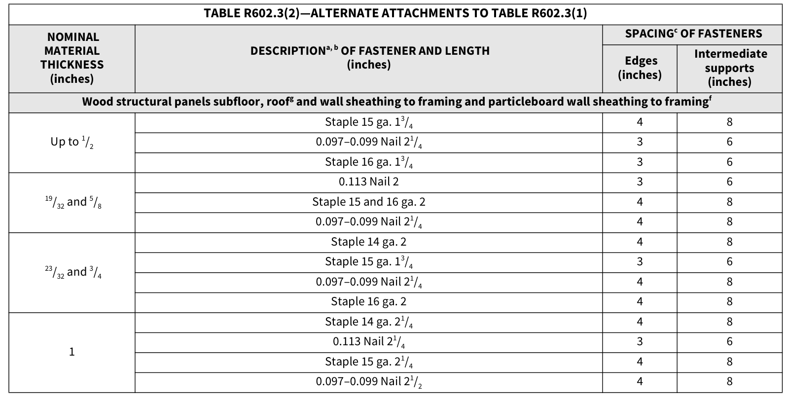
TABLE R602.3(2)—ALTERNATE ATTACHMENTS TO TABLE R602.3(1)¶
| Nominal material thickness (inches) | Descriptiona, b of fastener and length (inches) | Spacingc: edges (inches) | Spacingc: intermediate supports (inches) |
|---|---|---|---|
| Wood structural panels subfloor, roofg and wall sheathing to framing and particleboard wall sheathing to framingf | |||
| Up to 1/2 | Staple 15 ga. 1¾ | 4 | 8 |
| Up to 1/2 | 0.097–0.099 Nail 2¼ | 3 | 6 |
| Up to 1/2 | Staple 16 ga. 1¾ | 3 | 6 |
| 19/32 and 5/8 | 0.113 Nail 2 | 3 | 6 |
| 19/32 and 5/8 | Staple 15 and 16 ga. 2 | 4 | 8 |
| 19/32 and 5/8 | 0.097–0.099 Nail 2¼ | 4 | 8 |
| 23/32 and 3/4 | Staple 14 ga. 2 | 4 | 8 |
| 23/32 and 3/4 | Staple 15 ga. 1¾ | 3 | 6 |
| 23/32 and 3/4 | 0.097–0.099 Nail 2¼ | 4 | 8 |
| 23/32 and 3/4 | Staple 16 ga. 2 | 4 | 8 |
| 1 | Staple 14 ga. 2¼ | 4 | 8 |
| 1 | 0.113 Nail 2¼ | 3 | 6 |
| 1 | Staple 15 ga. 2¼ | 4 | 8 |
| 1 | 0.097–0.099 Nail 2½ | 4 | 8 |
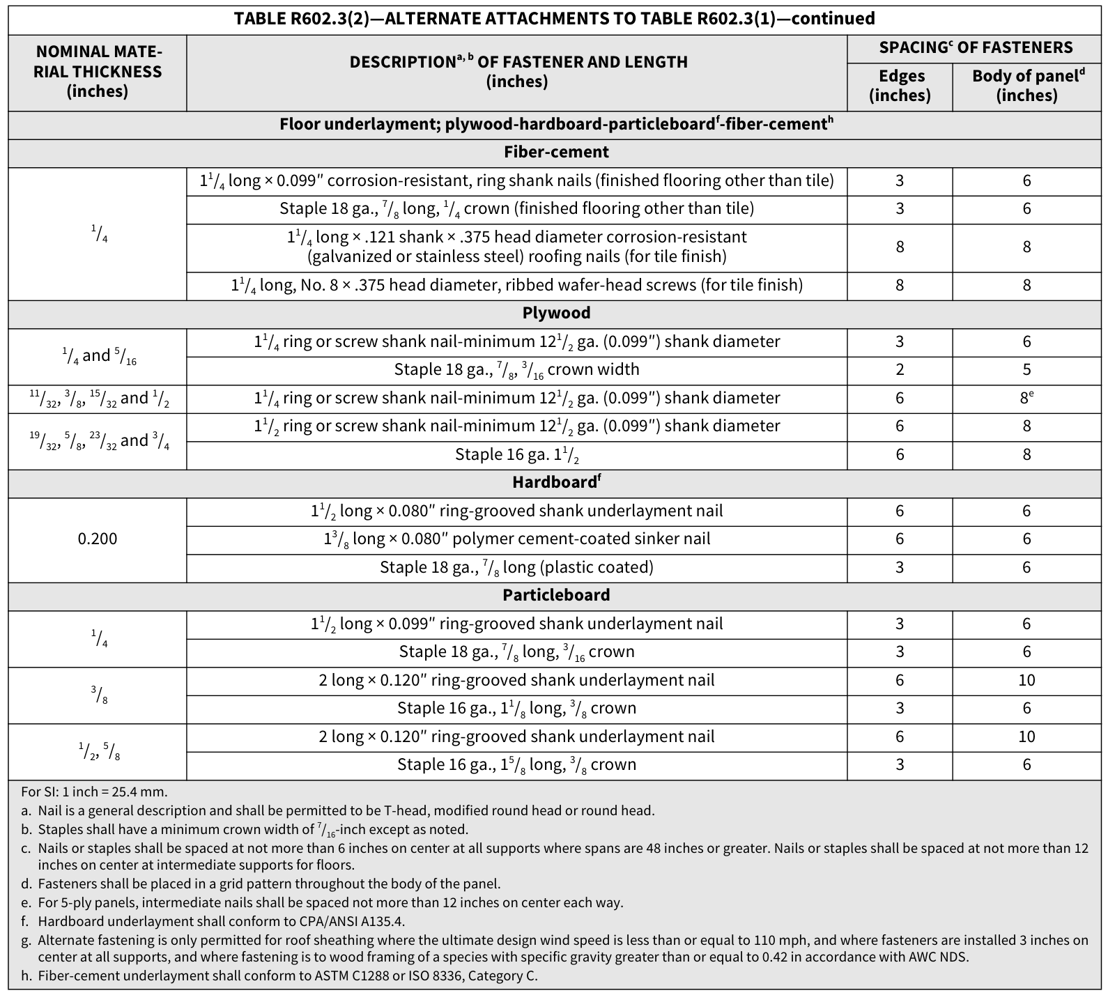
TABLE R602.3(2)—ALTERNATE ATTACHMENTS TO TABLE R602.3(1)—continued
| Nominal material thickness (inches) | Descriptiona, b of fastener and length (inches) | Spacingc: edges (inches) | Spacingc: body of paneld (inches) |
|---|---|---|---|
| Floor underlayment; plywood-hardboard-particleboardf-fiber-cementh | |||
| Fiber-cement | Fiber-cement | Fiber-cement | Fiber-cement |
| 1/4 | 1¼ long × 0.099″ corrosion-resistant, ring shank nails (finished flooring other than tile) | 3 | 6 |
| 1/4 | Staple 18 ga., 7/8 long, 1/4 crown (finished flooring other than tile) | 3 | 6 |
| 1/4 | 1¼ long × .121 shank × .375 head diameter corrosion-resistant (galvanized or stainless steel) roofing nails (for tile finish) |
8 | 8 |
| 1/4 | 1¼ long, No. 8 × .375 head diameter, ribbed wafer-head screws (for tile finish) | 8 | 8 |
| Plywood | Plywood | Plywood | Plywood |
| 1/4 and 5/16 | 1¼ ring or screw shank nail-minimum 12½ ga. (0.099″) shank diameter | 3 | 6 |
| 1/4 and 5/16 | Staple 18 ga., 7/8, 3/16 crown width | 2 | 5 |
| 11/32, 3/8, 15/32 and 1/2 | 1¼ ring or screw shank nail-minimum 12½ ga. (0.099″) shank diameter | 6 | 8e |
| 19/32, 5/8, 23/32 and 3/4 | 1½ ring or screw shank nail-minimum 12½ ga. (0.099″) shank diameter | 6 | 8 |
| 19/32, 5/8, 23/32 and 3/4 | Staple 16 ga. 1½ | 6 | 8 |
| Hardboardf | Hardboardf | Hardboardf | Hardboardf |
| 0.200 | 1½ long × 0.080″ ring-grooved shank underlayment nail | 6 | 6 |
| 0.200 | 1⅜ long × 0.080″ polymer cement-coated sinker nail | 6 | 6 |
| 0.200 | Staple 18 ga., 7/8 long (plastic coated) | 3 | 6 |
| Particleboard | Particleboard | Particleboard | Particleboard |
| 1/4 | 1½ long × 0.099″ ring-grooved shank underlayment nail | 3 | 6 |
| 1/4 | Staple 18 ga., 7/8 long, 3/16 crown | 3 | 6 |
| 3/8 | 2 long × 0.120″ ring-grooved shank underlayment nail | 6 | 10 |
| 3/8 | Staple 16 ga., 1⅛ long, 3/8 crown | 3 | 6 |
| 1/2, 5/8 | 2 long × 0.120″ ring-grooved shank underlayment nail | 6 | 10 |
| 1/2, 5/8 | Staple 16 ga., 1⅝ long, 3/8 crown | 3 | 6 |
For SI: 1 inch = 25.4 mm.
a. Nail is a general description and shall be permitted to be T-head, modified round head or round head.
b. Staples shall have a minimum crown width of 7/16-inch except as noted.
c. Nails or staples shall be spaced at not more than 6 inches on center at all supports where spans are 48 inches or greater. Nails or staples shall be spaced at not more than 12 inches on center at intermediate supports for floors.
d. Fasteners shall be placed in a grid pattern throughout the body of the panel.
e. For 5-ply panels, intermediate nails shall be spaced not more than 12 inches on center each way.
f. Hardboard underlayment shall conform to CPA/ANSI A135.4.
g. Alternate fastening is only permitted for roof sheathing where the ultimate design wind speed is less than or equal to 110 mph, and where fasteners are installed 3 inches on center at all supports, and where fastening is to wood framing of a species with specific gravity greater than or equal to 0.42 in accordance with AWC NDS.
h. Fiber-cement underlayment shall conform to ASTM C1288 or ISO 8336, Category C.
 Open full-size table ↗
 Open full-size table ↗
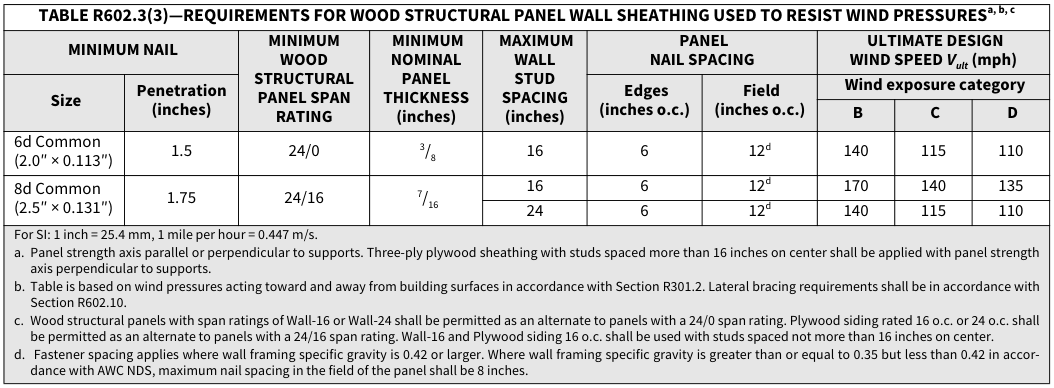
TABLE R602.3(3)—REQUIREMENTS FOR WOOD STRUCTURAL PANEL WALL SHEATHING USED TO RESIST…¶
TABLE R602.3(3)—REQUIREMENTS FOR WOOD STRUCTURAL PANEL WALL SHEATHING USED TO RESIST WIND PRESSURESa, b, c
| ** MINIMUM NAIL** | ** MINIMUM NAIL** | MINIMUM WOOD STRUCTURAL PANEL SPAN RATING |
** MINIMUM** NOMINAL PANEL THICKNESS (inches) |
** MAXIMUM** WALL STUD SPACING (inches) |
** PANEL** NAIL SPACING |
** PANEL** NAIL SPACING |
** ULTIMATE DESIGN** WIND SPEEDVult (mph) |
** ULTIMATE DESIGN** WIND SPEEDVult (mph) |
** ULTIMATE DESIGN** WIND SPEEDVult (mph) |
|---|---|---|---|---|---|---|---|---|---|
| ** Size** | ** Penetration** (inches) |
MINIMUM WOOD STRUCTURAL PANEL SPAN RATING |
** MINIMUM** NOMINAL PANEL THICKNESS (inches) |
** MAXIMUM** WALL STUD SPACING (inches) |
** Edges** (inches o.c.) |
** Field** (inches o.c.) |
** Wind exposure category** | ** Wind exposure category** | ** Wind exposure category** |
| ** Size** | ** Penetration** (inches) |
MINIMUM WOOD STRUCTURAL PANEL SPAN RATING |
** MINIMUM** NOMINAL PANEL THICKNESS (inches) |
** MAXIMUM** WALL STUD SPACING (inches) |
** Edges** (inches o.c.) |
** Field** (inches o.c.) |
** B** | ** C** | ** D** |
| 6d Common (2.0″ × 0.113″) |
1.5 | 24/0 | 3/8 | 16 | 6 | 12d | 140 | 115 | 110 |
| 8d Common (2.5″ × 0.131″) |
1.75 | 24/16 | 7/16 | 16 | 6 | 12d | 170 | 140 | 135 |
| 8d Common (2.5″ × 0.131″) |
1.75 | 24/16 | 7/16 | 24 | 6 | 12d | 140 | 115 | 110 |
For SI: 1 inch = 25.4 mm, 1 mile per hour = 0.447 m/s. a. Panel strength axis parallel or perpendicular to supports. Three-ply plywood sheathing with studs spaced more than 16 inches on center shall be applied with panel strength axis perpendicular to supports. b. Table is based on wind pressures acting toward and away from building surfaces in accordance with Section R301.2. Lateral bracing requirements shall be in accordance with Section R602.10. c. Wood structural panels with span ratings of Wall-16 or Wall-24 shall be permitted as an alternate to panels with a 24/0 span rating. Plywood siding rated 16 o.c. or 24 o.c. shall be permitted as an alternate to panels with a 24/16 span rating. Wall-16 and Plywood siding 16 o.c. shall be used with studs spaced not more than 16 inches on center. d. Fastener spacing applies where wall framing specific gravity is 0.42 or larger. Where wall framing specific gravity is greater than or equal to 0.35 but less than 0.42 in accor- dance with AWC NDS, maximum nail spacing in the field of the panel shall be 8 inches.
 Open full-size table ↗
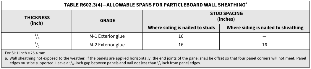
TABLE R602.3(4)—ALLOWABLE SPANS FOR PARTICLEBOARD WALL SHEATHINGa¶
TABLE R602.3(4)—ALLOWABLE SPANS FOR PARTICLEBOARD WALL SHEATHINGa
| ** THICKNESS** (inch) |
** GRADE** | ** STUD SPACING** (inches) |
** STUD SPACING** (inches) |
|---|---|---|---|
| ** THICKNESS** (inch) |
** GRADE** | ** Where siding is nailed to studs** | ** Where siding is nailed to sheathing** |
| 3/8 | M-1 Exterior glue | 16 | — |
| 1/2 | M-2 Exterior glue | 16 | 16 |
For SI: 1 inch = 25.4 mm. a. Wall sheathing not exposed to the weather. If the panels are applied horizontally, the end joints of the panel shall be offset so that four panel corners will not meet. Panel edges must be supported. Leave a1/16-inch gap between panels and nail not less than3/8 inch from panel edges.
 Open full-size table ↗
TABLE R602.3(5)—SIZE, HEIGHT AND SPACING OF WOOD STUDSa¶
TABLE R602.3(5)—SIZE, HEIGHT AND SPACING OF WOOD STUDSa
| ** STUD** SIZE (inches) |
** BEARING WALLS** | ** BEARING WALLS** | ** BEARING WALLS** | ** BEARING WALLS** | ** BEARING WALLS** | ** NONBEARING WALLS** | ** NONBEARING WALLS** |
|---|---|---|---|---|---|---|---|
| ** STUD** SIZE (inches) |
** Laterally** unsupported stud heighta (feet) |
** Maximum** spacing where supporting a roof-ceiling assembly or a habitable attic assembly, only (inches) |
** Maximum** spacing where supporting one floor, plus a roof- ceiling assembly or a habitable attic assembly (inches) |
** Maximum** spacing where supporting two floors, plus a roof-ceiling assembly or a habitable attic assembly (inches) |
** Maximum** spacing where supporting one floor heighta (inches) |
** Laterally** unsupported stud heighta (feet) |
Maximum spacing (inches) |
| 2 × 3b | — | — | — | — | — | 10 | 16 |
| 2 × 4 | 10 | 24c | 16c | — | 24 | 14 | 24 |
| 3 × 4 | 10 | 24 | 24 | 16 | 24 | 14 | 24 |
| 2 × 5 | 10 | 24 | 24 | — | 24 | 16 | 24 |
| 2 × 6 | 10 | 24 | 24 | 16 | 24 | 20 | 24 |
For SI: 1 inch = 25.4 mm, 1 foot = 304.8 mm. a. Listed heights are distances between points of lateral support placed perpendicular to the plane of the wall. Bearing walls shall be sheathed on not less than one side or bridg- ing shall be installed not greater than 4 feet apart measured vertically from either end of the stud. Increases in unsupported height are permitted where in compliance with Exception 2 of Section R602.3.1 or designed in accordance with accepted engineering practice. b. Shall not be used in exterior walls. c. A habitable attic assembly supported by 2 × 4 studs is limited to a roof span of 32 feet. Where the roof span exceeds 32 feet, the wall studs shall be increased to 2 × 6 or the studs shall be designed in accordance with accepted engineering practice.
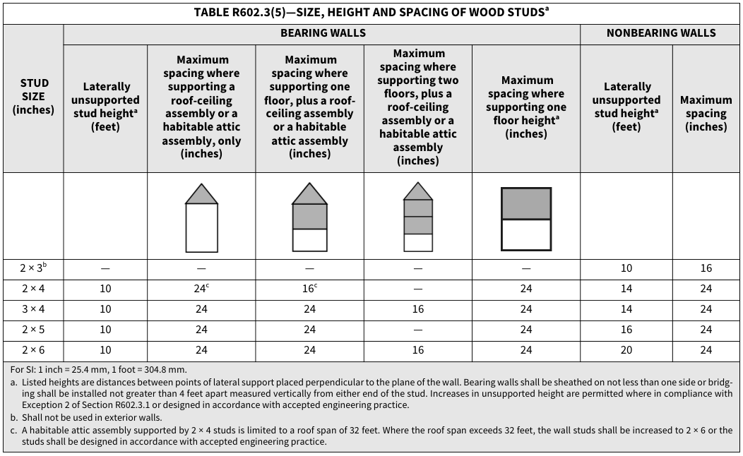 Open full-size table ↗
TABLE R602.3(6)—ALTERNATE WOOD BEARING WALL STUD SIZE, HEIGHT AND SPACING¶
TABLE R602.3(6)—ALTERNATE WOOD BEARING WALL STUD SIZE, HEIGHT AND SPACING
| ** STUD** HEIGHT |
** SUPPORTING** | ** STUD** SPACINGa |
** ULTIMATE DESIGN WIND SPEED** | ** ULTIMATE DESIGN WIND SPEED** | ** ULTIMATE DESIGN WIND SPEED** | ** ULTIMATE DESIGN WIND SPEED** | ** ULTIMATE DESIGN WIND SPEED** | ** ULTIMATE DESIGN WIND SPEED** |
|---|---|---|---|---|---|---|---|---|
| ** STUD** HEIGHT |
** SUPPORTING** | ** STUD** SPACINGa |
** 115 mph** | ** 115 mph** | ** 130 mphb** | ** 130 mphb** | ** 140 mphb** | ** 140 mphb** |
| ** STUD** HEIGHT |
** SUPPORTING** | ** STUD** SPACINGa |
** Maximum roof/ |
** Maximum roof/ |
** Maximum roof/ |
** Maximum roof/ |
** Maximum roof/ |
** Maximum roof/ |
| ** STUD** HEIGHT |
** SUPPORTING** | ** STUD** SPACINGa |
** 12 ft** | ** 24 ft** | ** 12 ft** | ** 24 ft** | ** 12 ft** | ** 24 ft** |
| 11 ft | Roof only | 12 in | 2 × 4 | 2 × 4 | 2 × 4 | 2 × 4 | 2 × 4 | 2 × 4 |
| 11 ft | Roof only | 16 in | 2 × 4 | 2 × 4 | 2 × 4 | 2 × 6 | 2 × 4 | 2 × 6 |
| 11 ft | Roof only | 24 in | 2 × 6 | 2 × 6 | 2 × 6 | 2 × 6 | 2 × 6 | 2 × 6 |
| 11 ft | Roof and one floor |
12 in | 2 × 4 | 2 × 6 | 2 × 4 | 2 × 6 | 2 × 4 | 2 × 6 |
| 11 ft | Roof and one floor |
16 in | 2 × 6 | 2 × 6 | 2 × 6 | 2 × 6 | 2 × 6 | 2 × 6 |
| 11 ft | Roof and one floor |
24 in | 2 × 6 | 2 × 6 | 2 × 6 | 2 × 6 | 2 × 6 | 2 × 6 |
| 12 ft | Roof only | 12 in | 2 × 4 | 2 × 4 | 2 × 4 | 2 × 6 | 2 × 4 | 2 × 6 |
| 12 ft | Roof only | 16 in | 2 × 4 | 2 × 6 | 2 × 6 | 2 × 6 | 2 × 6 | 2 × 6 |
| 12 ft | Roof only | 24 in | 2 × 6 | 2 × 6 | 2 × 6 | 2 × 6 | 2 × 6 | 2 × 6 |
| 12 ft | Roof and one floor |
12 in | 2 × 4 | 2 × 6 | 2 × 6 | 2 × 6 | 2 × 6 | 2 × 6 |
| 12 ft | Roof and one floor |
16 in | 2 × 6 | 2 × 6 | 2 × 6 | 2 × 6 | 2 × 6 | 2 × 6 |
| 12 ft | Roof and one floor |
24 in | 2 × 6 | 2 × 6 | 2 × 6 | 2 × 6 | 2 × 6 | DR |
For SI: 1 inch = 25.4 mm, 1 foot = 304.8 mm, 1 mph = 0.447 m/s, 1 pound = 4.448 N. DR = Design Required. a. Wall studs not exceeding 16 inches on center shall be sheathed with minimum1/2-inch gypsum board on the interior and3/8-inch wood structural panel sheathing on the exte- rior. Wood structural panel sheathing shall be attached with 8d (2.5″ × 0.131″) nails not greater than 6 inches on center along panel edges and 12 inches on center at intermediate supports, and all panel joints shall occur over studs or blocking. b. Where the ultimate design wind speed exceeds 115 mph, studs shall be attached to top and bottom plates with connectors having a minimum 300-pound lateral capacity. c. The maximum span is applicable to both single- and multiple-span roof and floor conditions. The roof assembly shall not contain a habitable attic.
SEE DRILLING AND
NOTCHING PROVISIONS
SECTION R602.6.1
SEE DRILLING AND
NOTCHING PROVISIONS
SECTION R602.6
JOIST NAILED TO
1 IN. x 4 IN. RIBBON
CUT INTO STUD—
SEE SECTION R502.6
SEE SECTION R602.8
FOR FIREBLOCKING
FIGURE R602.3(1)—TYPICAL WALL, FLOOR AND ROOF FRAMING
FIGURE R602.3(2)—FRAMING DETAILS
FIREBLOCK AROUND PIPE
WALL STUDS SEE SECTION R602.3
BOTTOM PLATE
STAGGER JOINTS 24 IN. OR
SEE SECTION R602.3.2
FULL-HEIGHT STUDS ADJACENT TO HEADER SEE SECTION R602.7.5
HEADER— SEE TABLES R602.7(1) AND R602.7(2)
SOLID BLOCKING
FLOOR JOISTS
FOUNDATION CRIPPLE WALL— SEE SECTION R602.9
FOUNDATION WALL STUDS
| JACK STUDS OR TRIMMERS |
JACK STUDS OR TRIMMERS |
JACK STUDS OR TRIMMERS |
JACK STUDS OR TRIMMERS |
JACK STUDS OR TRIMMERS |
JACK STUDS OR TRIMMERS |
JACK STUDS OR TRIMMERS |
JACK STUDS OR TRIMMERS |
JACK STUDS OR TRIMMERS |
JACK STUDS OR TRIMMERS |
JACK STUDS OR TRIMMERS |
JACK STUDS OR TRIMMERS |
||||||||||||||||||
APPLY APPROVED SHEATHING OR BRACE EXTERIOR WALLS WITH 1 IN. BY 4 IN. BRACES LET INTO STUDS AND PLATES AND EXTENDING FROM BOTTOM PLATE TO TOP PLATE, OR OTHER APPROVED METAL STRAP DEVICES INSTALLED IN ACCORDANCE WITH THE MANUFACTURER’S SPECIFICATIONS. SEE SECTION R602.10.
For SI: 1 inch = 25.4 mm, 1 foot = 304.8 mm.
NOTE: A THIRD STUD AND/OR PARTITION INTERSECTION BACKING STUDS SHALL BE PERMITTED TO BE OMITTED THROUGH THE USE OF WOOD BACKUP CLEATS, METAL DRYWALL CLIPS OR OTHER APPROVED DEVICES THAT WILL SERVE AS ADEQUATE BACKING FOR THE FACING MATERIALS.
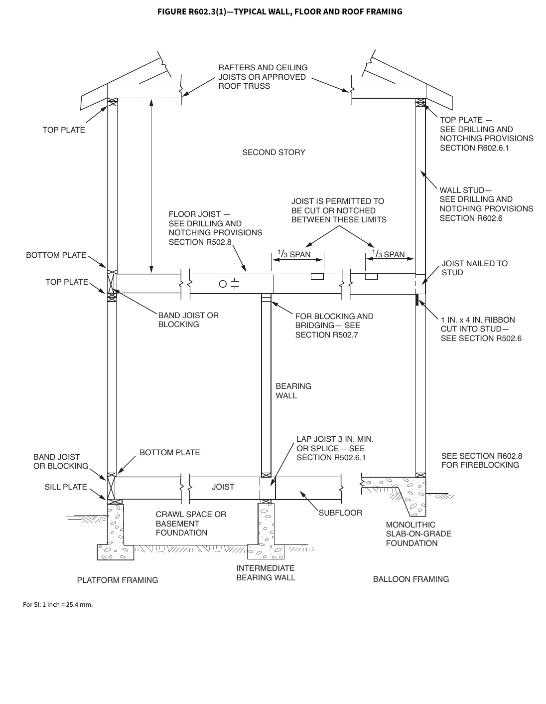 Open full-size illustration ↗
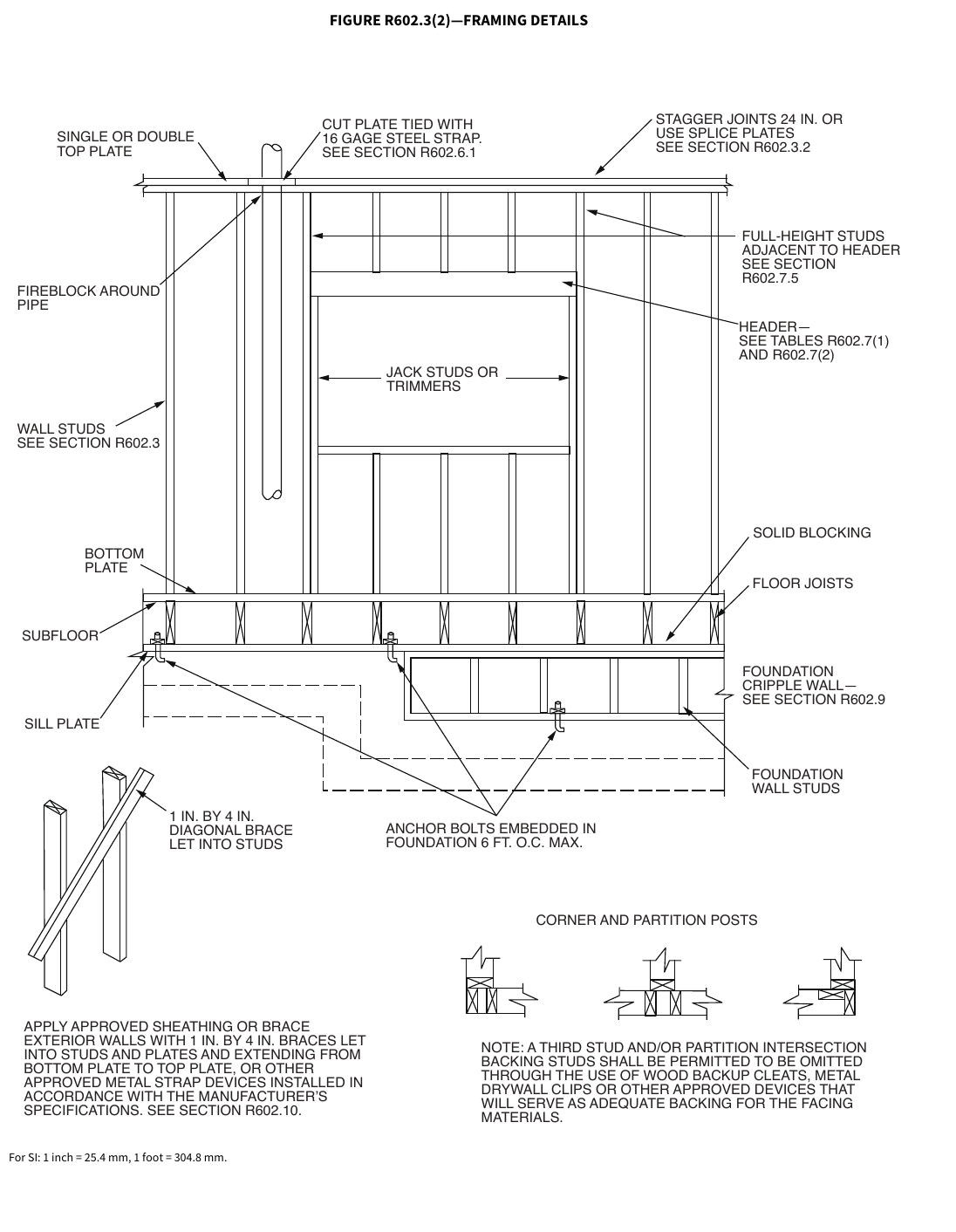 Open full-size illustration ↗
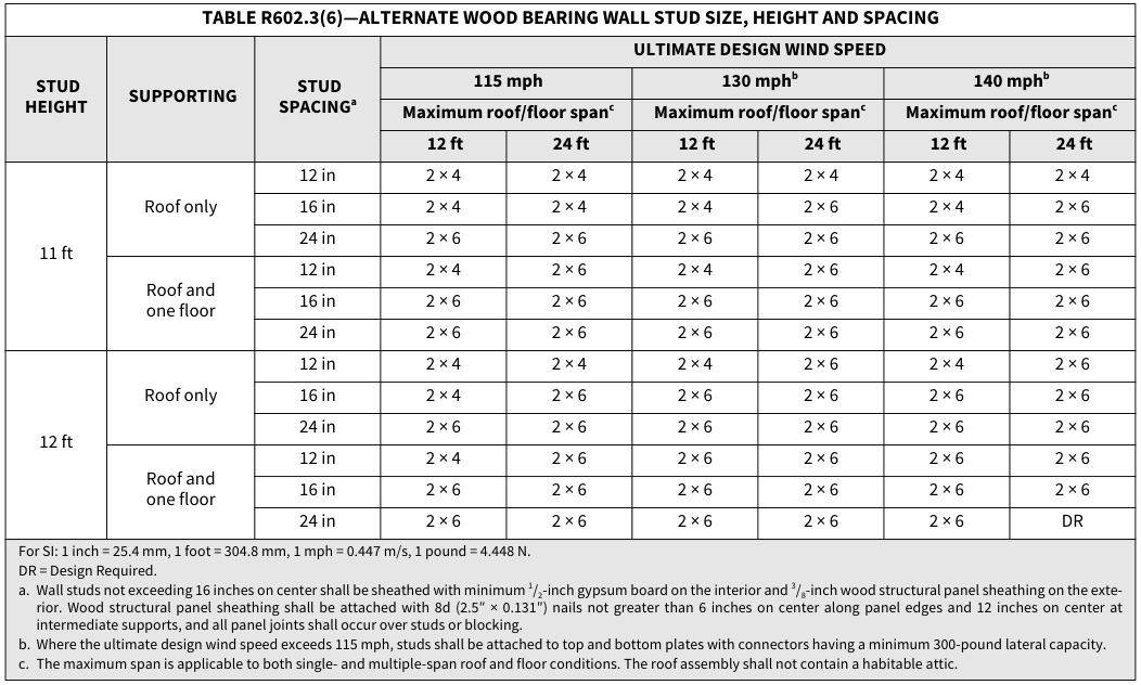 Open full-size table ↗
R602.3.1 Stud size, height and spacing.¶
The size, height and spacing of studs shall be in accordance with Table R602.3(5).
Exceptions:
- Utility grade studs shall not be spaced more than 16 inches (406 mm) on center, shall not support more than a roof and ceiling, and shall not exceed 8 feet (2438 mm) in height for exterior walls and load-bearing walls or 10 feet (3048 mm) for interior nonload-bearing walls.
- Where ground snow loads are less than or equal to 25 pounds per square foot (1.2 kPa), and the ultimate design wind speed is less than or equal to 130 mph (58.1 m/s), 2-inch by 6-inch (38 mm by 140 mm) studs supporting a roof load with not more than 6 feet (1829 mm) of tributary length shall have a maximum height of 18 feet (5486 mm) where spaced at 16 inches (406 mm) on center, or 20 feet (6096 mm) where spaced at 12 inches (305 mm) on center. Studs shall be No. 2 grade lumber or better.
- Exterior load-bearing studs not exceeding 12 feet (3658 mm) in height provided in accordance with Table R602.3(6). The minimum number of full-height studs adjacent to openings shall be in accordance with Section R602.7.5. The building shall be located in Exposure B, the roof live load shall not exceed 20 psf (0.96 kPa), and the ground snow load shall not exceed 30 psf (1.4 kPa). Studs and plates shall be No. 2 grade lumber or better.
R602.3.2 Top plate.¶
Wood stud walls shall be capped with a double top plate installed to provide overlapping at corners and intersections with bearing partitions. End joints in top plates shall be offset not less than 24 inches (610 mm). Joints in plates need not occur over studs. Plates shall be not less than 2-inches (51 mm) nominal thickness and have a width not less than the width of the studs.
Exception: A single top plate used as an alternative to a double top plate shall comply with the following:
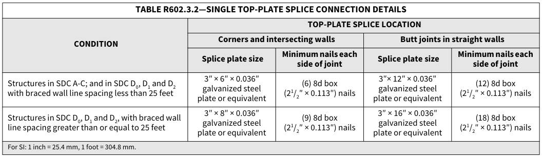
The single top plate shall be tied at corners, intersecting walls, and at in-line splices in straight wall lines in accordance with Table R602.3.2.
The rafters or joists shall be centered over the studs with a tolerance of not more than 1 inch (25 mm).
Omission of the top plate is permitted over headers where the headers are adequately tied to adjacent wall sections in accordance with Table R602.3.2.
TABLE R602.3.2—SINGLE TOP-PLATE SPLICE CONNECTION DETAILS¶
TABLE R602.3.2—SINGLE TOP-PLATE SPLICE CONNECTION DETAILS
| ** CONDITION** | ** TOP-PLATE SPLICE LOCATION** | ** TOP-PLATE SPLICE LOCATION** | ** TOP-PLATE SPLICE LOCATION** | ** TOP-PLATE SPLICE LOCATION** |
|---|---|---|---|---|
| ** CONDITION** | ** Corners and intersecting walls** | ** Corners and intersecting walls** | ** Butt joints in straight walls** | ** Butt joints in straight walls** |
| ** CONDITION** | ** Splice plate size** | ** Minimum nails each** side of joint |
** Splice plate size** | ** Minimum nails each** side of joint |
| Structures in SDC A-C; and in SDC D0, D1 and D2 with braced wall line spacing less than 25 feet |
3″ × 6″ × 0.036″ galvanized steel plate or equivalent |
(6) 8d box (2½″ × 0.113″) nails |
3″× 12″ × 0.036″ galvanized steel plate or equivalent |
(12) 8d box (2½″ × 0.113″) nails |
| Structures in SDC D0, D1 and D2, with braced wall line spacing greater than or equal to 25 feet |
3″ × 8″ × 0.036″ galvanized steel plate or equivalent |
(9) 8d box (2½″ × 0.113″) nails |
3″ × 16″ × 0.036″ galvanized steel plate or equivalent |
(18) 8d box (2½″ × 0.113″) nails |
For SI: 1 inch = 25.4 mm, 1 foot = 304.8 mm.
 Open full-size table ↗
R602.3.3 Bearing studs.¶
Where joists, trusses or rafters are spaced more than 16 inches (406 mm) on center and the bearing studs below are spaced 24 inches (610 mm) on center, such members shall bear within 5 inches (127 mm) of the studs beneath.
Exceptions:
- The top plates are two 2-inch by 6-inch (38 mm by 140 mm) or two 3-inch by 4-inch (64 mm by 89 mm) members.
- A third top plate is installed.
- Solid blocking equal in size to the studs is installed to reinforce the double top plate.
R602.3.4 Bottom (sole) plate.¶
Studs shall have full bearing on a nominal 2-by (51 mm) or larger plate or sill having a width not less than to the width of the studs.
R602.3.4.1 Rodent proofing. Annular spaces around pipes, electric cables, conduits or other openings in bottom/sole plates at exterior walls shall be protected against the passage of rodents by closing such openings in accordance with the California Green Building Standards Code, Chapter 4, Division 4.4.
R602.3.5 Braced wall panel uplift load path. Braced wall panels located at exterior walls that support roof rafters or trusses (including stories below top story) shall have the framing members connected in accordance with one of the following:
- Fastening in accordance with Table R602.3(1) where: 1.1. The ultimate design wind speed does not exceed 115 mph (51 m/s), the wind exposure category is B, the roof pitch is 5:12 or greater, and the roof span is 32 feet (9754 mm) or less.
1.2. The net uplift value at the top of a wall does not exceed 100 plf (146 N/mm). The net uplift value shall be determined in accordance with Section R802.11 and shall be permitted to be reduced by 60 plf (86 N/mm) for each full wall above.
- Where the net uplift value at the top of a wall exceeds 100 plf (146 N/mm), installing approved uplift framing connectors to provide a continuous load path from the top of the wall to the foundation or to a point where the uplift force is 100 plf (146 N/mm) or less. The net uplift value shall be as determined in Item 1.2.
- Wall sheathing and fasteners designed to resist combined uplift and shear forces in accordance with accepted engineering practice.
R602.4 Interior load-bearing walls.¶
Interior load-bearing walls shall be constructed, framed and fireblocked as specified for exterior walls.
R602.5 Interior nonbearing walls.¶
Interior nonbearing walls shall be permitted to be constructed with 2-inch by 3- inch (51 mm by 76 mm) studs spaced 24 inches (610 mm) on center or, where not part of a braced wall line, 2-inch by 4- inch (51 mm by 102 mm) flat studs spaced at 16 inches (406 mm) on center. Interior nonbearing walls shall be capped with not less than a single top plate. Interior nonbearing walls shall be fireblocked in accordance with Section R602.8.
R602.6 Drilling and notching of studs.¶
Drilling and notching of studs shall be in accordance with the following:
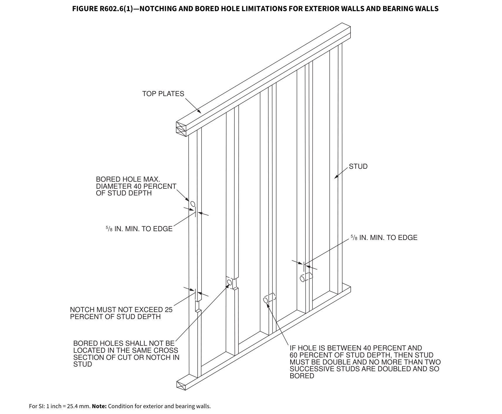
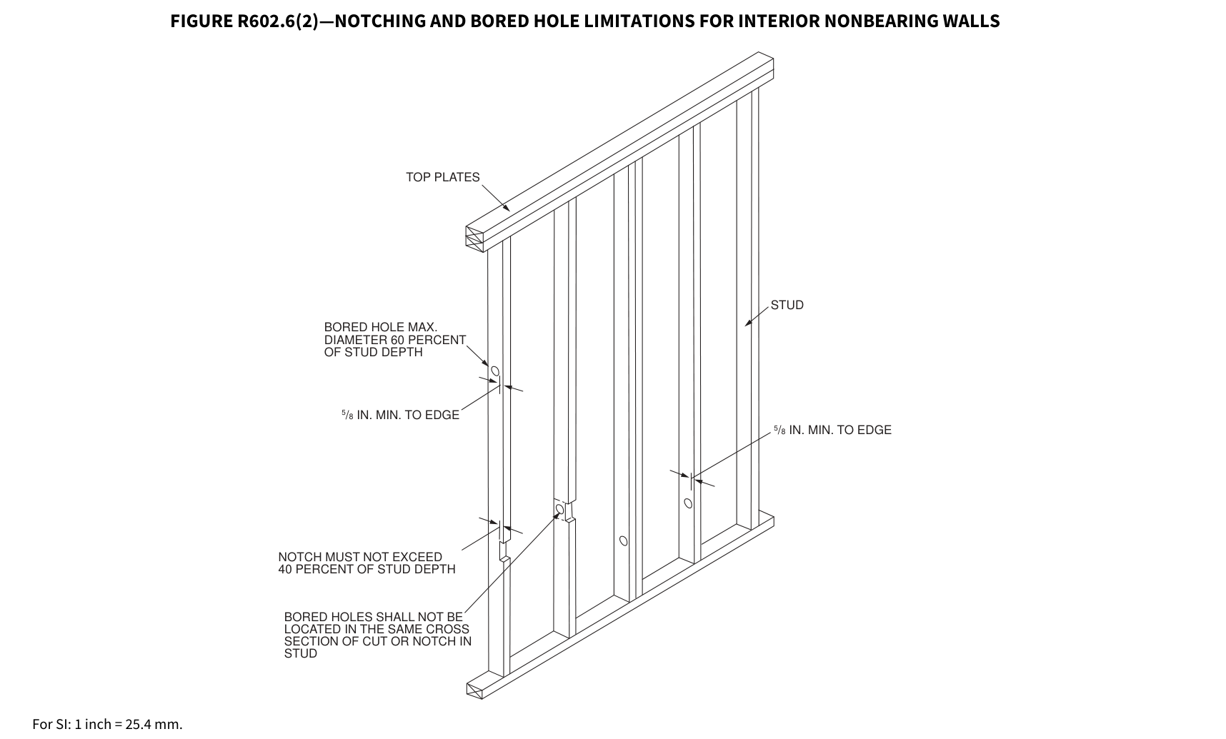
- Notching. A stud in an exterior wall or bearing partition shall not be cut or notched to a depth exceeding 25 percent of its depth. Studs in nonbearing partitions shall not be notched to a depth exceeding 40 percent of a single stud depth.
- Boring. The diameter of bored holes in studs shall not exceed 60 percent of the stud depth, the edge of the hole shall not be less than 5/8 inch (16 mm) from the edge of the stud, and the hole shall not be located in the same section as a cut or notch. Where the diameter of a bored hole in a stud located in exterior walls or bearing partitions is over 40 percent, such stud shall be doubled and not more than two successive doubled studs shall be so bored. See Figures R602.6(1) and R602.6(2).
Exception: Where approved, stud shoes are installed in accordance with the manufacturer’s instructions.
FIGURE R602.6(1)—NOTCHING AND BORED HOLE LIMITATIONS FOR EXTERIOR WALLS AND BEARING WALLS
TOP PLATES
STUD
BORED HOLE MAX. DIAMETER 40 PERCENT OF STUD DEPTH
5 / 8 IN. MIN. TO EDGE
5 / 8 IN. MIN. TO EDGE
NOTCH MUST NOT EXCEED 25 PERCENT OF STUD DEPTH
BORED HOLES SHALL NOT BE LOCATED IN THE SAME CROSS SECTION OF CUT OR NOTCH IN STUD
For SI: 1 inch = 25.4 mm. Note: Condition for exterior and bearing walls.
IF HOLE IS BETWEEN 40 PERCENT AND 60 PERCENT OF STUD DEPTH, THEN STUD MUST BE DOUBLE AND NO MORE THAN TWO SUCCESSIVE STUDS ARE DOUBLED AND SO
FIGURE R602.6(2)—NOTCHING AND BORED HOLE LIMITATIONS FOR INTERIOR NONBEARING WALLS
TOP PLATES
STUD
BORED HOLE MAX. DIAMETER 60 PERCENT OF STUD DEPTH
5 / 8 IN. MIN. TO EDGE
5 / 8 IN. MIN. TO EDGE
NOTCH MUST NOT EXCEED 40 PERCENT OF STUD DEPTH
BORED HOLES SHALL NOT BE LOCATED IN THE SAME CROSS SECTION OF CUT OR NOTCH IN STUD
For SI: 1 inch = 25.4 mm.
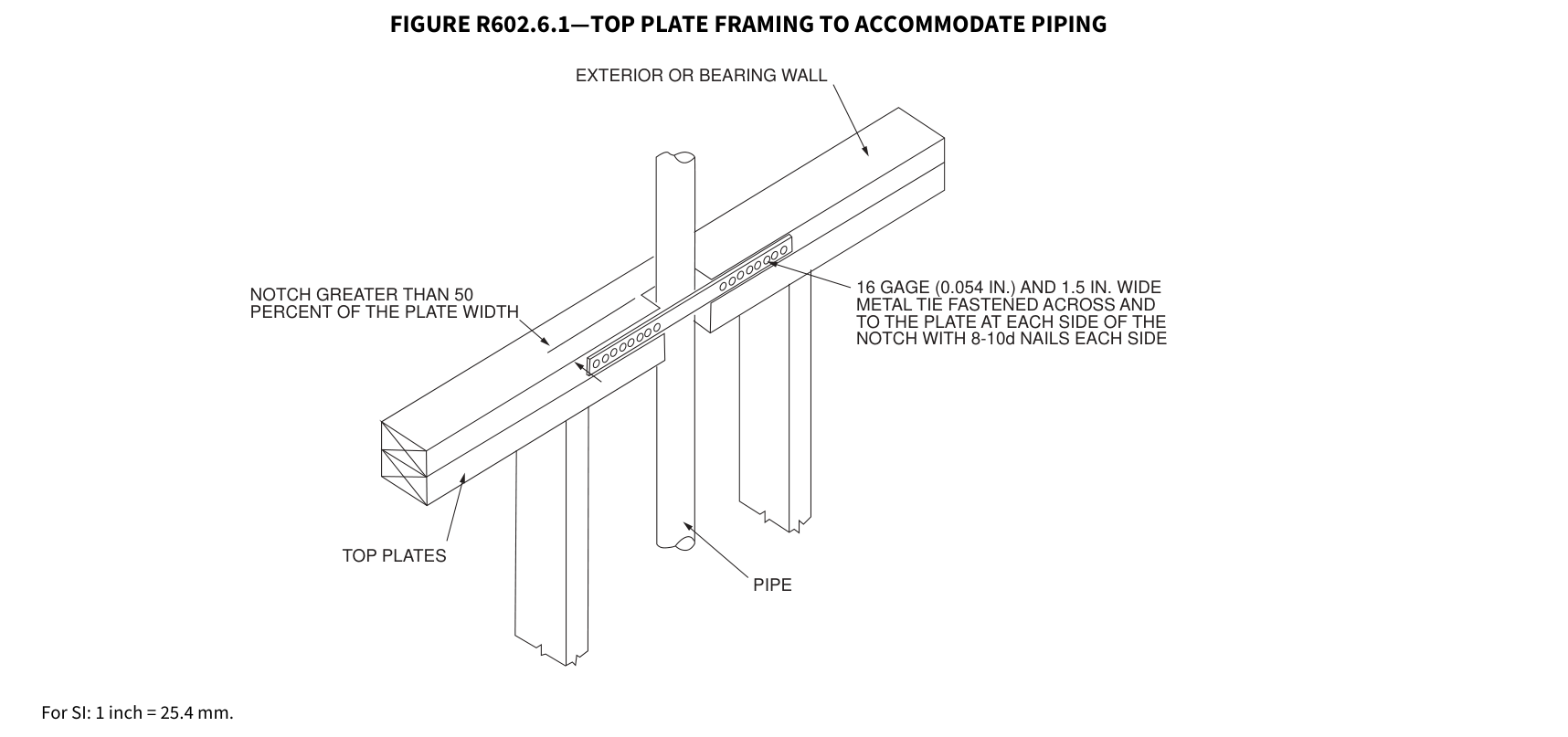
R602.6.1 Drilling and notching of top plate. Where piping or ductwork is placed in or partly in an exterior wall or interior loadbearing wall, necessitating cutting, drilling or notching of the top plate by more than 50 percent of its width, a galvanized metal tie not less than 0.054 inch thick (1.37 mm) (16 ga) and 1 1/2 inches (38 mm) wide shall be fastened across and to the plate at each side of the opening with not less than eight 10d (0.148 inch diameter) nails having a minimum length of 1 1/2 inches (38 mm) at each side or equivalent. The metal tie must extend not less than 6 inches past the opening. See Figure R602.6.1.
Exception: Where the entire side of the wall with the notch or cut is covered by wood structural panel sheathing.
FIGURE R602.6.1—TOP PLATE FRAMING TO ACCOMMODATE PIPING
EXTERIOR OR BEARING WALL
NOTCH GREATER THAN 50
16 GAGE (0.054 IN.) AND 1.5 IN. WIDE METAL TIE FASTENED ACROSS AND TO THE PLATE AT EACH SIDE OF THE NOTCH WITH 8-10d NAILS EACH SIDE
For SI: 1 inch = 25.4 mm.
 Open full-size illustration ↗
 Open full-size illustration ↗
 Open full-size illustration ↗
R602.7 Headers.¶
For header spans, see Tables R602.7(1), R602.7(2) and R602.7(3).
TABLE R602.7(1)—GIRDER SPANSa AND HEADER SPANSa FOR EXTERIOR BEARING WALLS
(Maximum spans for Douglas fir-larch, hem-fir, Southern pine and spruce-pine-firb and required number of jack studs)
| ** GIRDERS** AND HEADERS SUPPORTING |
** SIZE** | ** GROUND SNOW LOAD (psf)e ** | ** GROUND SNOW LOAD (psf)e ** | ** GROUND SNOW LOAD (psf)e ** | ** GROUND SNOW LOAD (psf)e ** | ** GROUND SNOW LOAD (psf)e ** | ** GROUND SNOW LOAD (psf)e ** | ** GROUND SNOW LOAD (psf)e ** | ** GROUND SNOW LOAD (psf)e ** | ** GROUND SNOW LOAD (psf)e ** | ** GROUND SNOW LOAD (psf)e ** | ** GROUND SNOW LOAD (psf)e ** | ** GROUND SNOW LOAD (psf)e ** | ** GROUND SNOW LOAD (psf)e ** | ** GROUND SNOW LOAD (psf)e ** | ** GROUND SNOW LOAD (psf)e ** | ** GROUND SNOW LOAD (psf)e ** | ** GROUND SNOW LOAD (psf)e ** | ** GROUND SNOW LOAD (psf)e ** |
|---|---|---|---|---|---|---|---|---|---|---|---|---|---|---|---|---|---|---|---|
| ** GIRDERS** AND HEADERS SUPPORTING |
** SIZE** | 30 | 30 | 30 | 30 | 30 | 30 | ** 50** | ** 50** | ** 50** | ** 50** | ** 50** | ** 50** | ** 70** | ** 70** | ** 70** | ** 70** | ** 70** | ** 70** |
| ** GIRDERS** AND HEADERS SUPPORTING |
** SIZE** | ** Building widthc (feet)** | ** Building widthc (feet)** | ** Building widthc (feet)** | ** Building widthc (feet)** | ** Building widthc (feet)** | ** Building widthc (feet)** | ** Building widthc (feet)** | ** Building widthc (feet)** | ** Building widthc (feet)** | ** Building widthc (feet)** | ** Building widthc (feet)** | ** Building widthc (feet)** | ** Building widthc (feet)** | ** Building widthc (feet)** | ** Building widthc (feet)** | ** Building widthc (feet)** | ** Building widthc (feet)** | ** Building widthc (feet)** |
| ** GIRDERS** AND HEADERS SUPPORTING |
** SIZE** | ** 12** |
** 12** |
** 24** |
** 24** |
** 36** |
** 36** |
** 12** |
** 12** |
** 24** |
** 24** |
** 36** |
** 36** |
** 12** |
** 12** |
** 24** |
** 24** |
** 36** | ** 36** |
| ** GIRDERS** AND HEADERS SUPPORTING |
** SIZE** | Spanf | NJd | Spanf | NJd | Spanf | NJd | Spanf | NJd | Spanf | NJd | Spanf | NJd | Spanf | NJd | Spanf | NJd | Spanf | NJd |
| Roof and ceiling | 1-2 × 6 | 4-0 | 1 | 3-1 | 2 | 2-7 | 2 | 3-5 | 1 | 2-8 | 2 | 2-3 | 2 | 3-0 | 2 | 2-4 | 2 | 2-0 | 2 |
| Roof and ceiling | 1-2 × 8 | 5-1 | 2 | 3-11 | 2 | 3-3 | 2 | 4-4 | 2 | 3-4 | 2 | 2-10 | 2 | 3-10 | 2 | 3-0 | 2 | 2-6 | 3 |
| Roof and ceiling | 1-2 × 10 | 6-0 | 2 | 4-8 | 2 | 3-11 | 2 | 5-2 | 2 | 4-0 | 2 | 3-4 | 3 | 4-7 | 2 | 3-6 | 3 | 3-0 | 3 |
| Roof and ceiling | 1-2 × 12 | 7-1 | 2 | 5-5 | 2 | 4-7 | 3 | 6-1 | 2 | 4-8 | 3 | 3-11 | 3 | 5-5 | 2 | 4-2 | 3 | 3-6 | 3 |
| Roof and ceiling | 2-2 × 4 | 4-0 | 1 | 3-1 | 1 | 2-7 | 1 | 3-5 | 1 | 2-7 | 1 | 2-2 | 1 | 3-0 | 1 | 2-4 | 1 | 2-0 | 1 |
| Roof and ceiling | 2-2 × 6 | 6-0 | 1 | 4-7 | 1 | 3-10 | 1 | 5-1 | 1 | 3-11 | 1 | 3-3 | 2 | 4-6 | 1 | 3-6 | 2 | 2-11 | 2 |
| Roof and ceiling | 2-2 × 8 | 7-7 | 1 | 5-9 | 1 | 4-10 | 2 | 6-5 | 1 | 5-0 | 2 | 4-2 | 2 | 5-9 | 1 | 4-5 | 2 | 3-9 | 2 |
| Roof and ceiling | 2-2 × 10 | 9-0 | 1 | 6-10 | 2 | 5-9 | 2 | 7-8 | 2 | 5-11 | 2 | 4-11 | 2 | 6-9 | 2 | 5-3 | 2 | 4-5 | 2 |
| Roof and ceiling | 2-2 × 12 | 10-7 | 2 | 8-1 | 2 | 6-10 | 2 | 9-0 | 2 | 6-11 | 2 | 5-10 | 2 | 8-0 | 2 | 6-2 | 2 | 5-2 | 3 |
| Roof and ceiling | 3-2 × 8 | 9-5 | 1 | 7-3 | 1 | 6-1 | 1 | 8-1 | 1 | 6-3 | 1 | 5-3 | 2 | 7-2 | 1 | 5-6 | 2 | 4-8 | 2 |
| Roof and ceiling | 3-2 × 10 | 11-3 | 1 | 8-7 | 1 | 7-3 | 2 | 9-7 | 1 | 7-4 | 2 | 6-2 | 2 | 8-6 | 1 | 6-7 | 2 | 5-6 | 2 |
| Roof and ceiling | 3-2 × 12 | 13-2 | 1 | 10-1 | 2 | 8-6 | 2 | 11-3 | 2 | 8-8 | 2 | 7-4 | 2 | 10-0 | 2 | 7-9 | 2 | 6-6 | 2 |
| Roof and ceiling | 4-2 × 8 | 10-11 | 1 | 8-4 | 1 | 7-0 | 1 | 9-4 | 1 | 7-2 | 1 | 6-0 | 1 | 8-3 | 1 | 6-4 | 1 | 5-4 | 2 |
| Roof and ceiling | 4-2 × 10 | 12-11 | 1 | 9-11 | 1 | 8-4 | 1 | 11-1 | 1 | 8-6 | 1 | 7-2 | 2 | 9-10 | 1 | 7-7 | 2 | 6-4 | 2 |
| Roof and ceiling | 4-2 × 12 | 15-3 | 1 | 11-8 | 1 | 9-10 | 2 | 13-0 | 1 | 10-0 | 2 | 8-5 | 2 | 11-7 | 1 | 8-11 | 2 | 7-6 | 2 |
| Roof, ceiling and one center- bearing floor |
1-2 × 6 | 3-3 | 1 | 2-7 | 2 | 2-2 | 2 | 3-0 | 2 | 2-4 | 2 | 2-0 | 2 | 2-9 | 2 | 2-2 | 2 | 1-10 | 2 |
| Roof, ceiling and one center- bearing floor |
1-2 × 8 | 4-1 | 2 | 3-3 | 2 | 2-9 | 2 | 3-9 | 2 | 3-0 | 2 | 2-6 | 3 | 3-6 | 2 | 2-9 | 2 | 2-4 | 3 |
| Roof, ceiling and one center- bearing floor |
1-2 × 10 | 4-11 | 2 | 3-10 | 2 | 3-3 | 3 | 4-6 | 2 | 3-6 | 3 | 3-0 | 3 | 4-1 | 2 | 3-3 | 3 | 2-9 | 3 |
| Roof, ceiling and one center- bearing floor |
1-2 × 12 | 5-9 | 2 | 4-6 | 3 | 3-10 | 3 | 5-3 | 2 | 4-2 | 3 | 3-6 | 3 | 4-10 | 3 | 3-10 | 3 | 3-3 | 4 |
| Roof, ceiling and one center- bearing floor |
2-2 × 4 | 3-3 | 1 | 2-6 | 1 | 2-2 | 1 | 3-0 | 1 | 2-4 | 1 | 2-0 | 1 | 2-8 | 1 | 2-2 | 1 | 1-10 | 1 |
| Roof, ceiling and one center- bearing floor |
2-2 × 6 | 4-10 | 1 | 3-9 | 1 | 3-3 | 2 | 4-5 | 1 | 3-6 | 2 | 3-0 | 2 | 4-1 | 1 | 3-3 | 2 | 2-9 | 2 |
| Roof, ceiling and one center- bearing floor |
2-2 × 8 | 6-1 | 1 | 4-10 | 2 | 4-1 | 2 | 5-7 | 2 | 4-5 | 2 | 3-9 | 2 | 5-2 | 2 | 4-1 | 2 | 3-6 | 2 |
| Roof, ceiling and one center- bearing floor |
2-2 × 10 | 7-3 | 2 | 5-8 | 2 | 4-10 | 2 | 6-8 | 2 | 5-3 | 2 | 4-5 | 2 | 6-1 | 2 | 4-10 | 2 | 4-1 | 2 |
| Roof, ceiling and one center- bearing floor |
2-2 × 12 | 8-6 | 2 | 6-8 | 2 | 5-8 | 2 | 7-10 | 2 | 6-2 | 2 | 5-3 | 3 | 7-2 | 2 | 5-8 | 2 | 4-10 | 3 |
| Roof, ceiling and one center- bearing floor |
3-2 × 8 | 7-8 | 1 | 6-0 | 1 | 5-1 | 2 | 7-0 | 1 | 5-6 | 2 | 4-8 | 2 | 6-5 | 1 | 5-1 | 2 | 4-4 | 2 |
| Roof, ceiling and one center- bearing floor |
3-2 × 10 | 9-1 | 1 | 7-2 | 2 | 6-1 | 2 | 8-4 | 1 | 6-7 | 2 | 5-7 | 2 | 7-8 | 2 | 6-1 | 2 | 5-2 | 2 |
| Roof, ceiling and one center- bearing floor |
3-2 × 12 | 10-8 | 2 | 8-5 | 2 | 7-2 | 2 | 9-10 | 2 | 7-8 | 2 | 6-7 | 2 | 9-0 | 2 | 7-1 | 2 | 6-1 | 2 |
| Roof, ceiling and one center- bearing floor |
4-2 × 8 | 8-10 | 1 | 6-11 | 1 | 5-11 | 1 | 8-1 | 1 | 6-4 | 1 | 5-5 | 2 | 7-5 | 1 | 5-11 | 1 | 5-0 | 2 |
| Roof, ceiling and one center- bearing floor |
4-2 × 10 | 10-6 | 1 | 8-3 | 2 | 7-0 | 2 | 9-8 | 1 | 7-7 | 2 | 6-5 | 2 | 8-10 | 1 | 7-0 | 2 | 6-0 | 2 |
| Roof, ceiling and one center- bearing floor |
4-2 × 12 | 12-4 | 1 | 9-8 | 2 | 8-3 | 2 | 11-4 | 2 | 8-11 | 2 | 7-7 | 2 | 10-4 | 2 | 8-3 | 2 | 7-0 | 2 |
TABLE R602.7(1)—GIRDER SPANSa AND HEADER SPANSa FOR EXTERIOR BEARING WALLS
(Maximum spans for Douglas fir-larch, hem-fir, Southern pine and spruce-pine-firb and required number of jack studs)—continued
TABLE R602.7(1)—GIRDER SPANSa AND HEADER SPANSa FOR EXTERIOR BEARING WALLS
(Maximum spans for Douglas fir-larch, hem-fir, Southern pine and spruce-pine-firb and required number of jack studs)
| ** GIRDERS** AND HEADERS SUPPORTING |
** SIZE** | ** GROUND SNOW LOAD (psf)e ** | ** GROUND SNOW LOAD (psf)e ** | ** GROUND SNOW LOAD (psf)e ** | ** GROUND SNOW LOAD (psf)e ** | ** GROUND SNOW LOAD (psf)e ** | ** GROUND SNOW LOAD (psf)e ** | ** GROUND SNOW LOAD (psf)e ** | ** GROUND SNOW LOAD (psf)e ** | ** GROUND SNOW LOAD (psf)e ** | ** GROUND SNOW LOAD (psf)e ** | ** GROUND SNOW LOAD (psf)e ** | ** GROUND SNOW LOAD (psf)e ** | ** GROUND SNOW LOAD (psf)e ** | ** GROUND SNOW LOAD (psf)e ** | ** GROUND SNOW LOAD (psf)e ** | ** GROUND SNOW LOAD (psf)e ** | ** GROUND SNOW LOAD (psf)e ** | ** GROUND SNOW LOAD (psf)e ** |
|---|---|---|---|---|---|---|---|---|---|---|---|---|---|---|---|---|---|---|---|
| ** GIRDERS** AND HEADERS SUPPORTING |
** SIZE** | 30 | 30 | 30 | 30 | 30 | 30 | ** 50** | ** 50** | ** 50** | ** 50** | ** 50** | ** 50** | ** 70** | ** 70** | ** 70** | ** 70** | ** 70** | ** 70** |
| ** GIRDERS** AND HEADERS SUPPORTING |
** SIZE** | ** Building widthc (feet)** | ** Building widthc (feet)** | ** Building widthc (feet)** | ** Building widthc (feet)** | ** Building widthc (feet)** | ** Building widthc (feet)** | ** Building widthc (feet)** | ** Building widthc (feet)** | ** Building widthc (feet)** | ** Building widthc (feet)** | ** Building widthc (feet)** | ** Building widthc (feet)** | ** Building widthc (feet)** | ** Building widthc (feet)** | ** Building widthc (feet)** | ** Building widthc (feet)** | ** Building widthc (feet)** | ** Building widthc (feet)** |
| ** GIRDERS** AND HEADERS SUPPORTING |
** SIZE** | ** 12** |
** 12** |
** 24** |
** 24** |
** 36** |
** 36** |
** 12** |
** 12** |
** 24** |
** 24** |
** 36** |
** 36** |
** 12** |
** 12** |
** 24** |
** 24** |
** 36** | ** 36** |
| ** GIRDERS** AND HEADERS SUPPORTING |
** SIZE** | Spanf | NJd | Spanf | NJd | Spanf | NJd | Spanf | NJd | Spanf | NJd | Spanf | NJd | Spanf | NJd | Spanf | NJd | Spanf | NJd |
| Roof, ceiling and one clear-span floor |
1-2 × 6 | 2-11 | 2 | 2-3 | 2 | 1-11 | 2 | 2-9 | 2 | 2-1 | 2 | 1-9 | 2 | 2-7 | 2 | 2-0 | 2 | 1-8 | 2 |
| Roof, ceiling and one clear-span floor |
1-2 × 8 | 3-9 | 2 | 2-10 | 2 | 2-5 | 3 | 3-6 | 2 | 2-8 | 2 | 2-3 | 3 | 3-3 | 2 | 2-6 | 3 | 2 -2 | 3 |
| Roof, ceiling and one clear-span floor |
1-2 × 10 | 4-5 | 2 | 3-5 | 3 | 2-10 | 3 | 4-2 | 2 | 3-2 | 3 | 2-8 | 3 | 3-11 | 2 | 3-0 | 3 | 2-6 | 3 |
| Roof, ceiling and one clear-span floor |
1-2 × 12 | 5-2 | 2 | 4-0 | 3 | 3-4 | 3 | 4-10 | 3 | 3-9 | 3 | 3-2 | 4 | 4-7 | 3 | 3-6 | 3 | 3-0 | 4 |
| Roof, ceiling and one clear-span floor |
2-2 × 4 | 2-11 | 1 | 2-3 | 1 | 1-10 | 1 | 2-9 | 1 | 2-1 | 1 | 1-9 | 1 | 2-7 | 1 | 2-0 | 1 | 1-8 | 1 |
| Roof, ceiling and one clear-span floor |
2-2 × 6 | 4-4 | 1 | 3-4 | 2 | 2-10 | 2 | 4-1 | 1 | 3-2 | 2 | 2-8 | 2 | 3-10 | 1 | 3-0 | 2 | 2-6 | 2 |
| Roof, ceiling and one clear-span floor |
2-2 × 8 | 5-6 | 2 | 4-3 | 2 | 3-7 | 2 | 5-2 | 2 | 4-0 | 2 | 3-4 | 2 | 4-10 | 2 | 3-9 | 2 | 3-2 | 2 |
| Roof, ceiling and one clear-span floor |
2-2 × 10 | 6-7 | 2 | 5-0 | 2 | 4-2 | 2 | 6-1 | 2 | 4-9 | 2 | 4-0 | 2 | 5-9 | 2 | 4-5 | 2 | 3-9 | 3 |
| Roof, ceiling and one clear-span floor |
2-2 × 12 | 7-9 | 2 | 5-11 | 2 | 4-11 | 3 | 7-2 | 2 | 5-7 | 2 | 4-8 | 3 | 6-9 | 2 | 5-3 | 3 | 4-5 | 3 |
| Roof, ceiling and one clear-span floor |
3-2 × 8 | 6-11 | 1 | 5-3 | 2 | 4-5 | 2 | 6-5 | 1 | 5-0 | 2 | 4-2 | 2 | 6-1 | 1 | 4-8 | 2 | 4-0 | 2 |
| Roof, ceiling and one clear-span floor |
3-2 × 10 | 8-3 | 2 | 6-3 | 2 | 5-3 | 2 | 7-8 | 2 | 5-11 | 2 | 5-0 | 2 | 7-3 | 2 | 5-7 | 2 | 4-8 | 2 |
| Roof, ceiling and one clear-span floor |
3-2 × 12 | 9-8 | 2 | 7-5 | 2 | 6-2 | 2 | 9-0 | 2 | 7-0 | 2 | 5-10 | 2 | 8-6 | 2 | 6-7 | 2 | 5-6 | 3 |
| Roof, ceiling and one clear-span floor |
4-2 × 8 | 8-0 | 1 | 6-1 | 1 | 5-1 | 2 | 7-5 | 1 | 5-9 | 2 | 4-10 | 2 | 7-0 | 1 | 5-5 | 2 | 4-7 | 2 |
| Roof, ceiling and one clear-span floor |
4-2 × 10 | 9-6 | 1 | 7-3 | 2 | 6-1 | 2 | 8-10 | 1 | 6-10 | 2 | 5-9 | 2 | 8-4 | 1 | 6-5 | 2 | 5-5 | 2 |
| Roof, ceiling and one clear-span floor |
4-2 × 12 | 11-2 | 2 | 8-6 | 2 | 7-2 | 2 | 10-5 | 2 | 8-0 | 2 | 6-9 | 2 | 9-10 | 2 | 7-7 | 2 | 6-5 | 2 |
| Roof, ceiling and two center-bearing floors |
1-2 × 6 | 2-8 | 2 | 2-1 | 2 | 1-10 | 2 | 2-7 | 2 | 2-0 | 2 | 1-9 | 2 | 2-5 | 2 | 1-11 | 2 | 1-8 | 2 |
| Roof, ceiling and two center-bearing floors |
1-2 × 8 | 3-5 | 2 | 2-8 | 2 | 2-4 | 3 | 3-3 | 2 | 2-7 | 2 | 2-2 | 3 | 3-1 | 2 | 2-5 | 3 | 2-1 | 3 |
| Roof, ceiling and two center-bearing floors |
1-2 × 10 | 4-0 | 2 | 3-2 | 3 | 2-9 | 3 | 3-10 | 2 | 3-1 | 3 | 2-7 | 3 | 3-8 | 2 | 2-11 | 3 | 2-5 | 3 |
| Roof, ceiling and two center-bearing floors |
1-2 × 12 | 4-9 | 3 | 3-9 | 3 | 3-2 | 4 | 4-6 | 3 | 3-7 | 3 | 3-1 | 4 | 4-3 | 3 | 3-5 | 3 | 2-11 | 4 |
| Roof, ceiling and two center-bearing floors |
2-2 × 4 | 2-8 | 1 | 2-1 | 1 | 1-9 | 1 | 2-6 | 1 | 2-0 | 1 | 1-8 | 1 | 2-5 | 1 | 1-11 | 1 | 1-7 | 1 |
| Roof, ceiling and two center-bearing floors |
2-2 × 6 | 4-0 | 1 | 3-2 | 2 | 2-8 | 2 | 3-9 | 1 | 3-0 | 2 | 2-7 | 2 | 3-7 | 1 | 2-10 | 2 | 2-5 | 2 |
| Roof, ceiling and two center-bearing floors |
2-2 × 8 | 5-0 | 2 | 4-0 | 2 | 3-5 | 2 | 4-10 | 2 | 3-10 | 2 | 3-3 | 2 | 4-7 | 2 | 3-7 | 2 | 3-1 | 2 |
| Roof, ceiling and two center-bearing floors |
2-2 × 10 | 6-0 | 2 | 4-9 | 2 | 4-0 | 2 | 5-8 | 2 | 4-6 | 2 | 3-10 | 3 | 5-5 | 2 | 4-3 | 2 | 3-8 | 3 |
| Roof, ceiling and two center-bearing floors |
2-2 × 12 | 7-0 | 2 | 5-7 | 2 | 4-9 | 3 | 6-8 | 2 | 5-4 | 3 | 4-6 | 3 | 6-4 | 2 | 5-0 | 3 | 4-3 | 3 |
| Roof, ceiling and two center-bearing floors |
3-2 × 8 | 6-4 | 1 | 5-0 | 2 | 4-3 | 2 | 6-0 | 1 | 4-9 | 2 | 4-1 | 2 | 5-8 | 2 | 4-6 | 2 | 3-10 | 2 |
| Roof, ceiling and two center-bearing floors |
3-2 × 10 | 7-6 | 2 | 5-11 | 2 | 5-1 | 2 | 7-1 | 2 | 5-8 | 2 | 4-10 | 2 | 6-9 | 2 | 5-4 | 2 | 4-7 | 2 |
| Roof, ceiling and two center-bearing floors |
3-2 × 12 | 8-10 | 2 | 7-0 | 2 | 5-11 | 2 | 8-5 | 2 | 6-8 | 2 | 5-8 | 3 | 8-0 | 2 | 6-4 | 2 | 5-4 | 3 |
| Roof, ceiling and two center-bearing floors |
4-2 × 8 | 7-3 | 1 | 5-9 | 1 | 4-11 | 2 | 6-11 | 1 | 5-6 | 2 | 4-8 | 2 | 6-7 | 1 | 5-2 | 2 | 4-5 | 2 |
| Roof, ceiling and two center-bearing floors |
4-2 × 10 | 8-8 | 1 | 6-10 | 2 | 5-10 | 2 | 8-3 | 2 | 6-6 | 2 | 5-7 | 2 | 7-10 | 2 | 6-2 | 2 | 5-3 | 2 |
| Roof, ceiling and two center-bearing floors |
4-2 × 12 | 10-2 | 2 | 8-1 | 2 | 6-10 | 2 | 9-8 | 2 | 7-8 | 2 | 6-7 | 2 | 9-2 | 2 | 7-3 | 2 | 6-2 | 2 |
TABLE R602.7(1)—GIRDER SPANSa AND HEADER SPANSa FOR EXTERIOR BEARING WALLS
(Maximum spans for Douglas fir-larch, hem-fir, Southern pine and spruce-pine-firb and required number of jack studs)
| ** GIRDERS** AND HEADERS SUPPORTING |
** SIZE** | ** GROUND SNOW LOAD (psf)e ** | ** GROUND SNOW LOAD (psf)e ** | ** GROUND SNOW LOAD (psf)e ** | ** GROUND SNOW LOAD (psf)e ** | ** GROUND SNOW LOAD (psf)e ** | ** GROUND SNOW LOAD (psf)e ** | ** GROUND SNOW LOAD (psf)e ** | ** GROUND SNOW LOAD (psf)e ** | ** GROUND SNOW LOAD (psf)e ** | ** GROUND SNOW LOAD (psf)e ** | ** GROUND SNOW LOAD (psf)e ** | ** GROUND SNOW LOAD (psf)e ** | ** GROUND SNOW LOAD (psf)e ** | ** GROUND SNOW LOAD (psf)e ** | ** GROUND SNOW LOAD (psf)e ** | ** GROUND SNOW LOAD (psf)e ** | ** GROUND SNOW LOAD (psf)e ** | ** GROUND SNOW LOAD (psf)e ** |
|---|---|---|---|---|---|---|---|---|---|---|---|---|---|---|---|---|---|---|---|
| ** GIRDERS** AND HEADERS SUPPORTING |
** SIZE** | 30 | 30 | 30 | 30 | 30 | 30 | ** 50** | ** 50** | ** 50** | ** 50** | ** 50** | ** 50** | ** 70** | ** 70** | ** 70** | ** 70** | ** 70** | ** 70** |
| ** GIRDERS** AND HEADERS SUPPORTING |
** SIZE** | ** Building widthc (feet)** | ** Building widthc (feet)** | ** Building widthc (feet)** | ** Building widthc (feet)** | ** Building widthc (feet)** | ** Building widthc (feet)** | ** Building widthc (feet)** | ** Building widthc (feet)** | ** Building widthc (feet)** | ** Building widthc (feet)** | ** Building widthc (feet)** | ** Building widthc (feet)** | ** Building widthc (feet)** | ** Building widthc (feet)** | ** Building widthc (feet)** | ** Building widthc (feet)** | ** Building widthc (feet)** | ** Building widthc (feet)** |
| ** GIRDERS** AND HEADERS SUPPORTING |
** SIZE** | ** 12** |
** 12** |
** 24** |
** 24** |
** 36** |
** 36** |
** 12** |
** 12** |
** 24** |
** 24** |
** 36** |
** 36** |
** 12** |
** 12** |
** 24** |
** 24** |
** 36** | ** 36** |
| ** GIRDERS** AND HEADERS SUPPORTING |
** SIZE** | Spanf | NJd | Spanf | NJd | Spanf | NJd | Spanf | NJd | Spanf | NJd | Spanf | NJd | Spanf | NJd | Spanf | NJd | Spanf | NJd |
| Roof, ceiling, and two clear-span floors |
1-2 × 6 | 2-3 | 2 | 1-9 | 2 | 1-5 | 2 | 2-3 | 2 | 1-9 | 2 | 1-5 | 3 | 2-2 | 2 | 1-8 | 2 | 1-5 | 3 |
| Roof, ceiling, and two clear-span floors |
1-2 × 8 | 2-10 | 2 | 2-2 | 3 | 1-10 | 3 | 2-10 | 2 | 2-2 | 3 | 1-10 | 3 | 2-9 | 2 | 2-1 | 3 | 1-10 | 3 |
| Roof, ceiling, and two clear-span floors |
1-2 × 10 | 3-4 | 2 | 2-7 | 3 | 2-2 | 3 | 3-4 | 3 | 2-7 | 3 | 2-2 | 4 | 3-3 | 3 | 2-6 | 3 | 2-2 | 4 |
| Roof, ceiling, and two clear-span floors |
1-2 × 12 | 4-0 | 3 | 3-0 | 3 | 2-7 | 4 | 4-0 | 3 | 3-0 | 4 | 2-7 | 4 | 3-10 | 3 | 3-0 | 4 | 2-6 | 4 |
| Roof, ceiling, and two clear-span floors |
2-2 × 4 | 2-3 | 1 | 1-8 | 1 | 1-4 | 1 | 2-3 | 1 | 1-8 | 1 | 1-4 | 1 | 2-2 | 1 | 1-8 | 1 | 1-4 | 2 |
| Roof, ceiling, and two clear-span floors |
2-2 × 6 | 3-4 | 1 | 2-6 | 2 | 2-2 | 2 | 3-4 | 2 | 2-6 | 2 | 2-2 | 2 | 3-3 | 2 | 2-6 | 2 | 2-1 | 2 |
| Roof, ceiling, and two clear-span floors |
2-2 × 8 | 4-3 | 2 | 3-3 | 2 | 2-8 | 2 | 4-3 | 2 | 3-3 | 2 | 2-8 | 2 | 4-1 | 2 | 3-2 | 2 | 2-8 | 3 |
| Roof, ceiling, and two clear-span floors |
2-2 × 10 | 5-0 | 2 | 3-10 | 2 | 3-2 | 3 | 5-0 | 2 | 3-10 | 2 | 3-2 | 3 | 4-10 | 2 | 3-9 | 3 | 3-2 | 3 |
| Roof, ceiling, and two clear-span floors |
2-2 × 12 | 5-11 | 2 | 4-6 | 3 | 3-9 | 3 | 5-11 | 2 | 4-6 | 3 | 3-9 | 3 | 5-8 | 2 | 4-5 | 3 | 3-9 | 3 |
| Roof, ceiling, and two clear-span floors |
3-2 × 8 | 5-3 | 1 | 4-0 | 2 | 3-5 | 2 | 5-3 | 2 | 4-0 | 2 | 3-5 | 2 | 5-1 | 2 | 3-11 | 2 | 3-4 | 2 |
| Roof, ceiling, and two clear-span floors |
3-2 × 10 | 6-3 | 2 | 4-9 | 2 | 4-0 | 2 | 6-3 | 2 | 4-9 | 2 | 4-0 | 2 | 6-1 | 2 | 4-8 | 2 | 4-0 | 3 |
| Roof, ceiling, and two clear-span floors |
3-2 × 12 | 7-5 | 2 | 5-8 | 2 | 4-9 | 3 | 7-5 | 2 | 5-8 | 2 | 4-9 | 3 | 7-2 | 2 | 5-6 | 3 | 4-8 | 3 |
| Roof, ceiling, and two clear-span floors |
4-2 × 8 | 6-1 | 1 | 4-8 | 2 | 3-11 | 2 | 6-1 | 1 | 4-8 | 2 | 3-11 | 2 | 5-11 | 1 | 4-7 | 2 | 3-10 | 2 |
| Roof, ceiling, and two clear-span floors |
4-2 × 10 | 7-3 | 2 | 5-6 | 2 | 4-8 | 2 | 7-3 | 2 | 5-6 | 2 | 4-8 | 2 | 7-0 | 2 | 5-5 | 2 | 4-7 | 2 |
| Roof, ceiling, and two clear-span floors |
4-2 × 12 | 8-6 | 2 | 6-6 | 2 | 5-6 | 2 | 8-6 | 2 | 6-6 | 2 | 5-6 | 2 | 8-3 | 2 | 6-4 | 2 | 5-4 | 3 |
For SI: 1 inch = 25.4 mm, 1 foot = 304.8 mm, 1 pound per square foot = 0.0479 kPa. a. Spans are given in feet and inches. b. Spans are based on minimum design properties for No. 2 grade lumber of Douglas fir-larch, hem-fir, Southern pine, and spruce-pine-fir. c. Building width is measured perpendicular to the ridge. For widths between those shown, spans are permitted to be interpolated. d. NJ = Number of jack studs required to support each end. Where the number of required jack studs equals one, the header is permitted to be supported by an approved fram- ing anchor attached to the full-height wall stud and to the header. e. Use 30 psf ground snow load for cases in which ground snow load is less than 30 psf and the roof live load is equal to or less than 20 psf. f. Spans are calculated assuming the top of the header or girder is laterally braced by perpendicular framing. Where the top of the header or girder is not laterally braced (for example, cripple studs bearing on the header), tabulated spans for headers consisting of 2 × 8, 2 × 10, or 2 × 12 sizes shall be multiplied by 0.70 or the header or girder shall be designed.
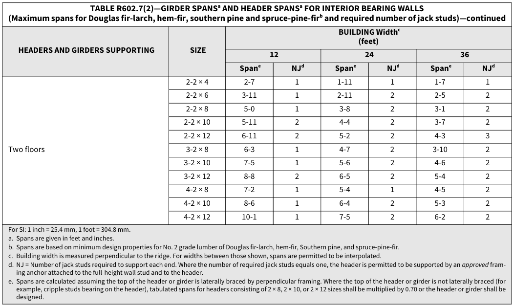
TABLE R602.7(2)—GIRDER SPANSa AND HEADER SPANSa FOR INTERIOR BEARING WALLS
(Maximum spans for Douglas fir-larch, hem-fir, southern pine and spruce-pine-firb and required number of jack studs)
| ** HEADERS AND GIRDERS SUPPORTING** | ** SIZE** | ** BUILDING Widthc (feet)** |
** BUILDING Widthc (feet)** |
** BUILDING Widthc (feet)** |
** BUILDING Widthc (feet)** |
** BUILDING Widthc (feet)** |
** BUILDING Widthc (feet)** |
|---|---|---|---|---|---|---|---|
| ** HEADERS AND GIRDERS SUPPORTING** | ** SIZE** | ** 12** | ** 12** | ** 24** | ** 24** | ** 36** | ** 36** |
| ** HEADERS AND GIRDERS SUPPORTING** | ** SIZE** | ** Spane** | ** NJd** | ** Spane** | ** NJd** | ** Spane** | ** NJd** |
| One floor only | 2-2 × 4 | 4-1 | 1 | 2-10 | 1 | 2-4 | 1 |
| One floor only | 2-2 × 6 | 6-1 | 1 | 4-4 | 1 | 3-6 | 1 |
| One floor only | 2-2 × 8 | 7-9 | 1 | 5-5 | 1 | 4-5 | 2 |
| One floor only | 2-2 × 10 | 9-2 | 1 | 6-6 | 2 | 5-3 | 2 |
| One floor only | 2-2 × 12 | 10-9 | 1 | 7-7 | 2 | 6-3 | 2 |
| One floor only | 3-2 × 8 | 9-8 | 1 | 6-10 | 1 | 5-7 | 1 |
| One floor only | 3-2 × 10 | 11-5 | 1 | 8-1 | 1 | 6-7 | 2 |
| One floor only | 3-2 × 12 | 13-6 | 1 | 9-6 | 2 | 7-9 | 2 |
| One floor only | 4-2 × 8 | 11-2 | 1 | 7-11 | 1 | 6-5 | 1 |
| One floor only | 4-2 × 10 | 13-3 | 1 | 9-4 | 1 | 7-8 | 1 |
| One floor only | 4-2 × 12 | 15-7 | 1 | 11-0 | 1 | 9-0 | 2 |
TABLE R602.7(2)—GIRDER SPANSa AND HEADER SPANSa FOR INTERIOR BEARING WALLS
(Maximum spans for Douglas fir-larch, hem-fir, southern pine and spruce-pine-firb and required number of jack studs)—continued
| ** HEADERS AND GIRDERS SUPPORTING** | ** SIZE** | ** BUILDING Widthc (feet)** |
** BUILDING Widthc (feet)** |
** BUILDING Widthc (feet)** |
** BUILDING Widthc (feet)** |
** BUILDING Widthc (feet)** |
** BUILDING Widthc (feet)** |
|---|---|---|---|---|---|---|---|
| ** HEADERS AND GIRDERS SUPPORTING** | ** SIZE** | ** 12** | ** 12** | ** 24** | ** 24** | ** 36** | ** 36** |
| ** HEADERS AND GIRDERS SUPPORTING** | ** SIZE** | ** Spane** | ** NJd** | ** Spane** | ** NJd** | ** Spane** | ** NJd** |
| Two floors | 2-2 × 4 | 2-7 | 1 | 1-11 | 1 | 1-7 | 1 |
| Two floors | 2-2 × 6 | 3-11 | 1 | 2-11 | 2 | 2-5 | 2 |
| Two floors | 2-2 × 8 | 5-0 | 1 | 3-8 | 2 | 3-1 | 2 |
| Two floors | 2-2 × 10 | 5-11 | 2 | 4-4 | 2 | 3-7 | 2 |
| Two floors | 2-2 × 12 | 6-11 | 2 | 5-2 | 2 | 4-3 | 3 |
| Two floors | 3-2 × 8 | 6-3 | 1 | 4-7 | 2 | 3-10 | 2 |
| Two floors | 3-2 × 10 | 7-5 | 1 | 5-6 | 2 | 4-6 | 2 |
| Two floors | 3-2 × 12 | 8-8 | 2 | 6-5 | 2 | 5-4 | 2 |
| Two floors | 4-2 × 8 | 7-2 | 1 | 5-4 | 1 | 4-5 | 2 |
| Two floors | 4-2 × 10 | 8-6 | 1 | 6-4 | 2 | 5-3 | 2 |
| Two floors | 4-2 × 12 | 10-1 | 1 | 7-5 | 2 | 6-2 | 2 |
For SI: 1 inch = 25.4 mm, 1 foot = 304.8 mm. a. Spans are given in feet and inches. b. Spans are based on minimum design properties for No. 2 grade lumber of Douglas fir-larch, hem-fir, Southern pine, and spruce-pine-fir. c. Building width is measured perpendicular to the ridge. For widths between those shown, spans are permitted to be interpolated. d. NJ = Number of jack studs required to support each end. Where the number of required jack studs equals one, the header is permitted to be supported by an_approved_ fram- ing anchor attached to the full-height wall stud and to the header. e. Spans are calculated assuming the top of the header or girder is laterally braced by perpendicular framing. Where the top of the header or girder is not laterally braced (for example, cripple studs bearing on the header), tabulated spans for headers consisting of 2 × 8, 2 × 10, or 2 × 12 sizes shall be multiplied by 0.70 or the header or girder shall be designed.
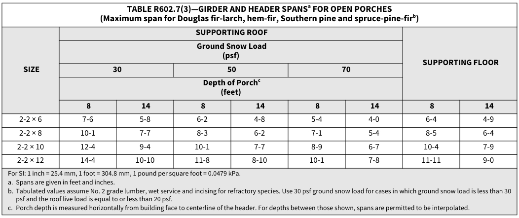
TABLE R602.7(3)—GIRDER AND HEADER SPANSa FOR OPEN PORCHES
(Maximum span for Douglas fir-larch, hem-fir, Southern pine and spruce-pine-firb)
| ** SIZE** | ** SUPPORTING ROOF** | ** SUPPORTING ROOF** | ** SUPPORTING ROOF** | ** SUPPORTING ROOF** | ** SUPPORTING ROOF** | ** SUPPORTING ROOF** | ** SUPPORTING FLOOR** | ** SUPPORTING FLOOR** |
|---|---|---|---|---|---|---|---|---|
| ** SIZE** | ** Ground Snow Load** (psf) |
** Ground Snow Load** (psf) |
** Ground Snow Load** (psf) |
** Ground Snow Load** (psf) |
** Ground Snow Load** (psf) |
** Ground Snow Load** (psf) |
** Ground Snow Load** (psf) |
** Ground Snow Load** (psf) |
| ** SIZE** | ** 30** | ** 30** | ** 50** | ** 50** | ** 70** | ** 70** | ** 70** | ** 70** |
| ** SIZE** | ** Depth of Porchc (feet)** |
** Depth of Porchc (feet)** |
** Depth of Porchc (feet)** |
** Depth of Porchc (feet)** |
** Depth of Porchc (feet)** |
** Depth of Porchc (feet)** |
** Depth of Porchc (feet)** |
** Depth of Porchc (feet)** |
| ** SIZE** | ** 8** | ** 14** | ** 8** | ** 14** | ** 8** | ** 14** | ** 8** | ** 14** |
| 2-2 × 6 | 7-6 | 5-8 | 6-2 | 4-8 | 5-4 | 4-0 | 6-4 | 4-9 |
| 2-2 × 8 | 10-1 | 7-7 | 8-3 | 6-2 | 7-1 | 5-4 | 8-5 | 6-4 |
| 2-2 × 10 | 12-4 | 9-4 | 10-1 | 7-7 | 8-9 | 6-7 | 10-4 | 7-9 |
| 2-2 × 12 | 14-4 | 10-10 | 11-8 | 8-10 | 10-1 | 7-8 | 11-11 | 9-0 |
For SI: 1 inch = 25.4 mm, 1 foot = 304.8 mm, 1 pound per square foot = 0.0479 kPa. a. Spans are given in feet and inches. b. Tabulated values assume No. 2 grade lumber, wet service and incising for refractory species. Use 30 psf ground snow load for cases in which ground snow load is less than 30 psf and the roof live load is equal to or less than 20 psf. c. Porch depth is measured horizontally from building face to centerline of the header. For depths between those shown, spans are permitted to be interpolated.
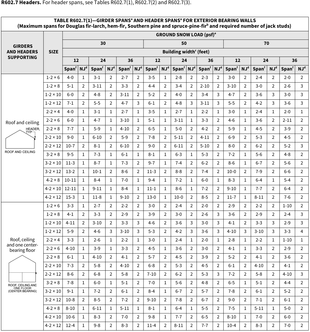 Open full-size table ↗
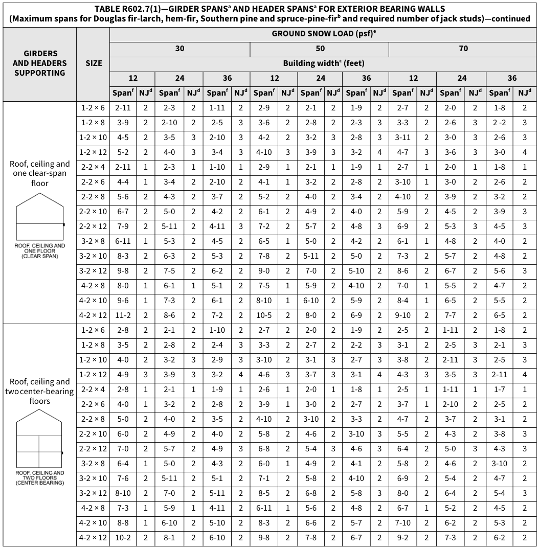 Open full-size table ↗
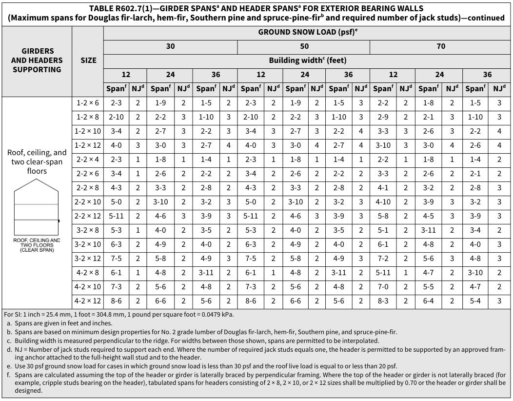 Open full-size table ↗
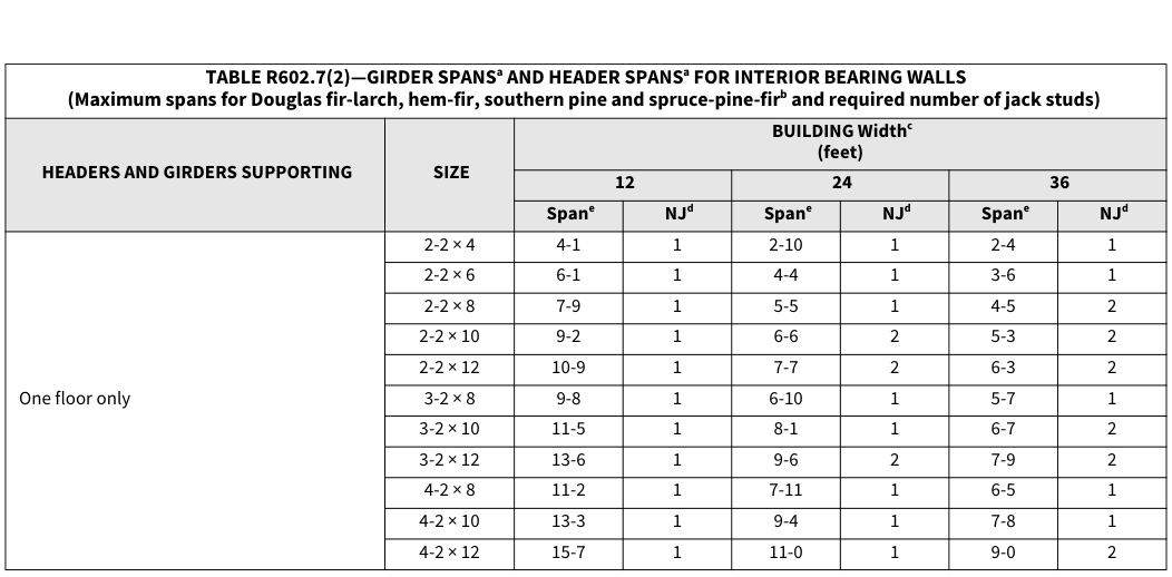 Open full-size table ↗
 Open full-size table ↗
 Open full-size table ↗
R602.7.1 Single member headers.¶
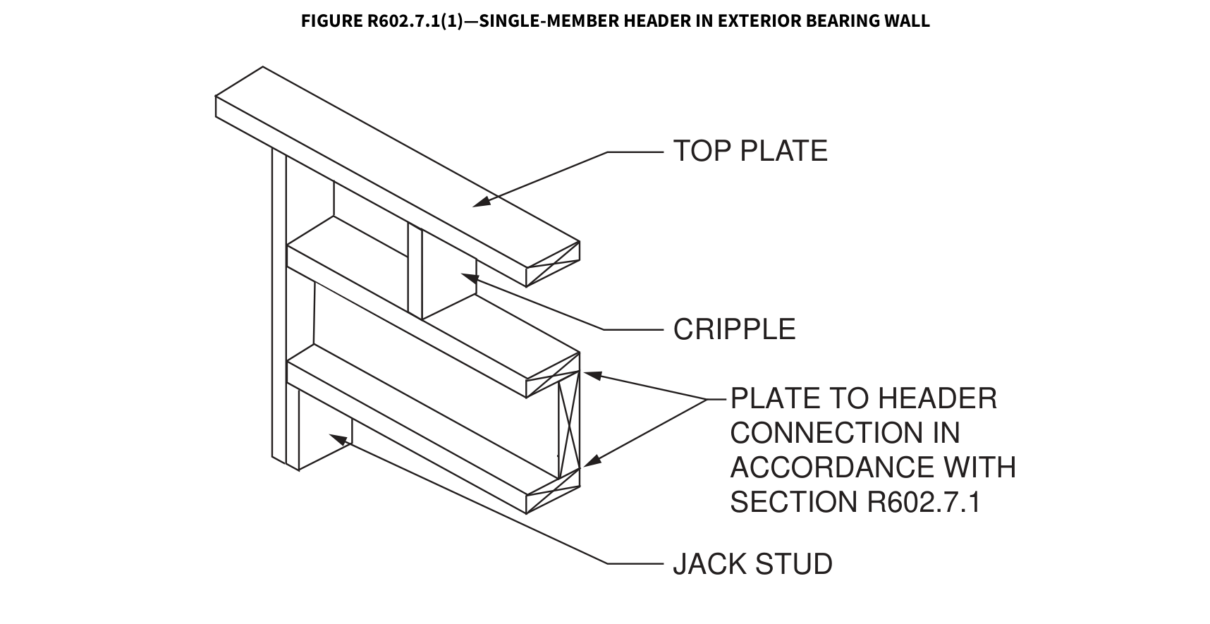
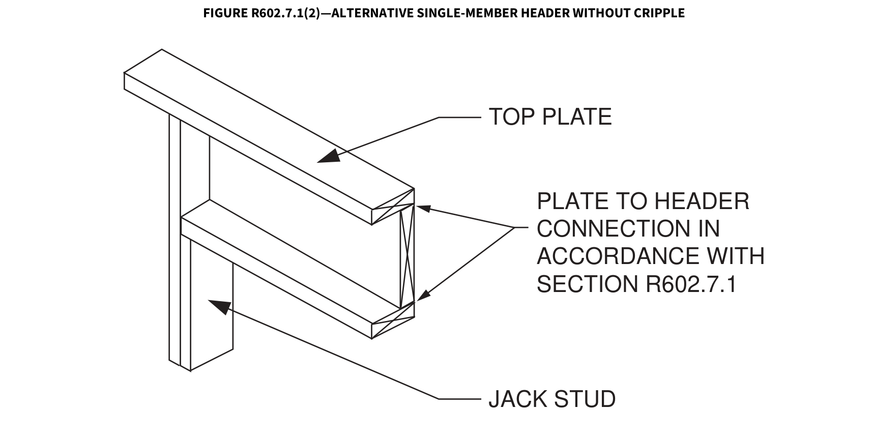
Single headers shall be framed with a single flat 2-inch-nominal (51 mm) member or wall plate not less in width than the wall studs on the top and bottom of the header in accordance with Figures R602.7.1(1) and R602.7.1(2) and face nailed to the top and bottom of the header with 10d box nails (3 inches × 0.128 inches) spaced 12 inches on
center.
FIGURE R602.7.1(1)—SINGLE-MEMBER HEADER IN EXTERIOR BEARING WALL
TOP PLATE
CRIPPLE
PLATE TO HEADER
CONNECTION IN
ACCORDANCE WITH
SECTION R602.7.1
JACK STUD
FIGURE R602.7.1(2)—ALTERNATIVE SINGLE-MEMBER HEADER WITHOUT CRIPPLE
TOP PLATE
PLATE TO HEADER
CONNECTION IN
ACCORDANCE WITH
SECTION R602.7.1
JACK STUD
 Open full-size illustration ↗
 Open full-size illustration ↗
R602.7.2 Rim board headers.¶
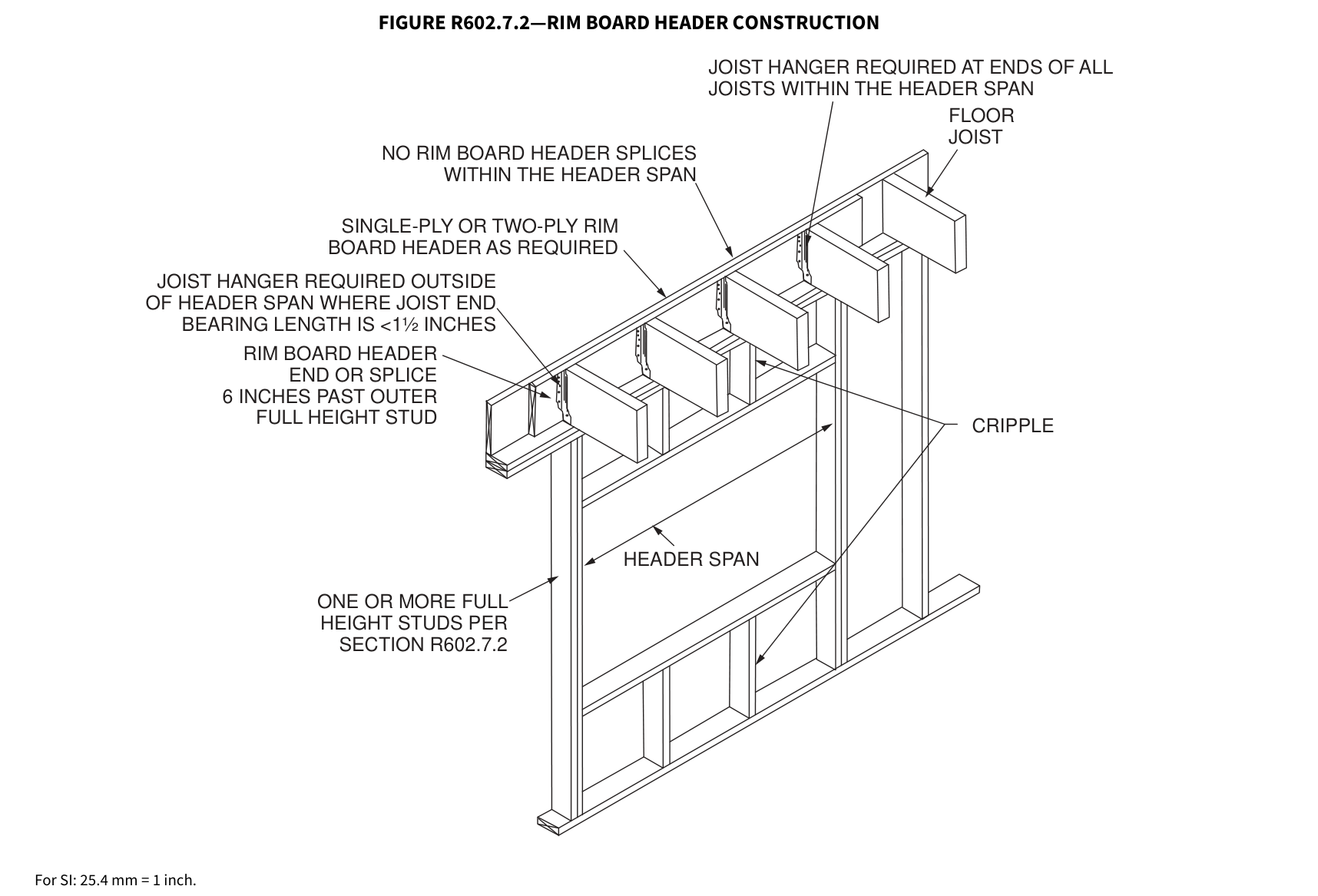
Rim board header size, material and span shall be in accordance with Table R602.7(1). Rim board headers shall be constructed in accordance with Figure R602.7.2 and shall be supported at each end by full-height studs. The number of full-height studs at each end shall be not less than one plus the number of studs displaced by half of the header span based on the maximum stud spacing in accordance with Table R602.3(5). Rim board headers supporting concentrated loads shall be designed in accordance with accepted engineering practice.
FIGURE R602.7.2—RIM BOARD HEADER CONSTRUCTION
JOIST HANGER REQUIRED AT ENDS OF ALL JOISTS WITHIN THE HEADER SPAN
FLOOR
JOIST HANGER REQUIRED OUTSIDE OF HEADER SPAN WHERE JOIST END BEARING LENGTH IS <1½ INCHES
RIM BOARD HEADER END OR SPLICE 6 INCHES PAST OUTER FULL HEIGHT STUD
ONE OR MORE FULL HEIGHT STUDS PER SECTION R602.7.2
CRIPPLE
For SI: 25.4 mm = 1 inch.
 Open full-size illustration ↗
R602.7.3 Wood structural panel box headers.¶
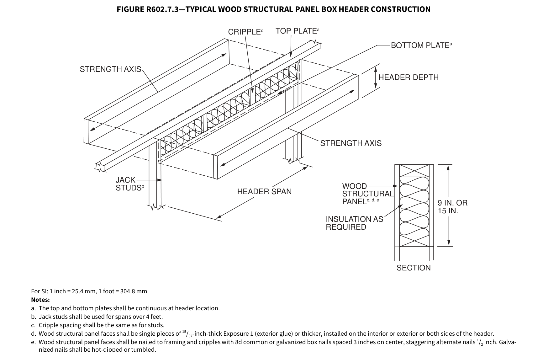
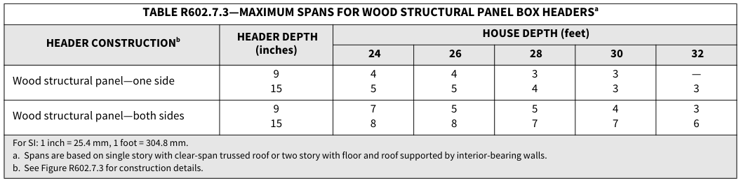
Wood structural panel box headers shall be constructed in accordance with Figure R602.7.3 and Table R602.7.3.
TABLE R602.7.3—MAXIMUM SPANS FOR WOOD STRUCTURAL PANEL BOX HEADERSa
| ** HEADER CONSTRUCTIONb** | ** HEADER DEPTH** (inches) |
** HOUSE DEPTH (feet)** | ** HOUSE DEPTH (feet)** | ** HOUSE DEPTH (feet)** | ** HOUSE DEPTH (feet)** | ** HOUSE DEPTH (feet)** |
|---|---|---|---|---|---|---|
| ** HEADER CONSTRUCTIONb** | ** HEADER DEPTH** (inches) |
** 24** | ** 26** | ** 28** | ** 30** | ** 32** |
| Wood structural panel—one side | 9 15 |
4 5 |
4 5 |
3 4 |
3 3 |
— 3 |
| Wood structural panel—both sides | 9 15 |
7 8 |
5 8 |
5 7 |
4 7 |
3 6 |
For SI: 1 inch = 25.4 mm, 1 foot = 304.8 mm. a. Spans are based on single story with clear-span trussed roof or two story with floor and roof supported by interior-bearing walls. b. See Figure R602.7.3 for construction details.
FIGURE R602.7.3—TYPICAL WOOD STRUCTURAL PANEL BOX HEADER CONSTRUCTION
9 IN. OR 15 IN.
| CRIPPLEc TOP PLATEa | |||
|---|---|---|---|
| INSULATION AS REQUIRED WOOD STRUCTURAL PANELc, d, e HEADER SPAN STRENGTH AXIS HEADER DEPT BOTTOM PL JACK STUDSb TRENGTH AXIS |
|||
| INSULATION AS REQUIRED WOOD STRUCTURAL PANELc, d, e HEADER SPAN STRENGTH AXIS HEADER DEPT BOTTOM PL JACK STUDSb TRENGTH AXIS |
|||
| INSULATION AS REQUIRED WOOD STRUCTURAL PANELc, d, e HEADER SPAN STRENGTH AXIS HEADER DEPT BOTTOM PL JACK STUDSb TRENGTH AXIS |
|||
| INSULATION AS REQUIRED WOOD STRUCTURAL PANELc, d, e HEADER SPAN STRENGTH AXIS HEADER DEPT BOTTOM PL JACK STUDSb TRENGTH AXIS |
|||
| INSULATION AS REQUIRED WOOD STRUCTURAL PANELc, d, e HEADER SPAN STRENGTH AXIS HEADER DEPT BOTTOM PL JACK STUDSb TRENGTH AXIS |
SECTION
For SI: 1 inch = 25.4 mm, 1 foot = 304.8 mm.
Notes:
a. The top and bottom plates shall be continuous at header location. b. Jack studs shall be used for spans over 4 feet. c. Cripple spacing shall be the same as for studs. d. Wood structural panel faces shall be single pieces of 15/32-inch-thick Exposure 1 (exterior glue) or thicker, installed on the interior or exterior or both sides of the header. e. Wood structural panel faces shall be nailed to framing and cripples with 8d common or galvanized box nails spaced 3 inches on center, staggering alternate nails 1/2 inch. Galvanized nails shall be hot-dipped or tumbled.
 Open full-size illustration ↗
 Open full-size table ↗
R602.7.4 Nonbearing walls.¶
Load-bearing headers are not required in interior or exterior nonbearing walls. A single flat 2-inch by 4-inch (51 mm by 102 mm) member shall be permitted to be used as a header in interior or exterior nonbearing walls for openings up to 8 feet (2438 mm) in width if the vertical distance to the parallel nailing surface above is not more than 24 inches (610 mm). For such nonbearing headers, cripples or blocking are not required above the header.
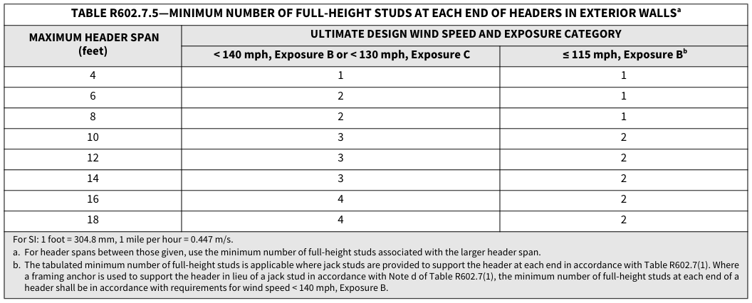
R602.7.5 Supports for headers. Headers shall be supported on each end with one or more jack studs or with approved framing anchors in accordance with Table R602.7(1) or R602.7(2). The full-height stud adjacent to each end of the header shall be end nailed to each end of the header in accordance with Table R602.3(1). The minimum number of full-height studs at each end of a header shall be in accordance with Table R602.7.5.
TABLE R602.7.5—MINIMUM NUMBER OF FULL-HEIGHT STUDS AT EACH END OF HEADERS IN EXTERIOR…¶
TABLE R602.7.5—MINIMUM NUMBER OF FULL-HEIGHT STUDS AT EACH END OF HEADERS IN EXTERIOR WALLSa
| ** MAXIMUM HEADER SPAN** (feet) |
** ULTIMATE DESIGN WIND SPEED AND EXPOSURE CATEGORY** | ** ULTIMATE DESIGN WIND SPEED AND EXPOSURE CATEGORY** |
|---|---|---|
| ** MAXIMUM HEADER SPAN** (feet) |
** < 140 mph, Exposure B or < 130 mph, Exposure C** | ** ≤ 115 mph, Exposure Bb** |
| 4 | 1 | 1 |
| 6 | 2 | 1 |
| 8 | 2 | 1 |
| 10 | 3 | 2 |
| 12 | 3 | 2 |
| 14 | 3 | 2 |
| 16 | 4 | 2 |
| 18 | 4 | 2 |
For SI: 1 foot = 304.8 mm, 1 mile per hour = 0.447 m/s. a. For header spans between those given, use the minimum number of full-height studs associated with the larger header span. b. The tabulated minimum number of full-height studs is applicable where jack studs are provided to support the header at each end in accordance with Table R602.7(1). Where a framing anchor is used to support the header in lieu of a jack stud in accordance with Note d of Table R602.7(1), the minimum number of full-height studs at each end of a header shall be in accordance with requirements for wind speed < 140 mph, Exposure B.
 Open full-size table ↗
R602.8 Fireblocking required.¶
Fireblocking shall be provided in accordance with Section R302.11.
R602.9 Cripple walls.¶
Foundation cripple walls shall be framed of studs not smaller than the studding above. Where exceeding 4 feet (1219 mm) in height, such walls shall be framed of studs having the size required for an additional story.
Exterior cripple walls with a stud height less than 14 inches (356 mm) shall be continuously sheathed on one side with wood structural panels fastened to both the top and bottom plates in accordance with Table R602.3(1), or the cripple walls shall be constructed of solid blocking.
Cripple walls shall be supported on continuous foundations.
R602.10 Wall bracing.¶
Buildings shall be braced in accordance with this section or, when applicable, Section R602.12. Where a building, or portion thereof, does not comply with one or more of the bracing requirements in this section, those portions shall be designed and constructed in accordance with Section R301.1.
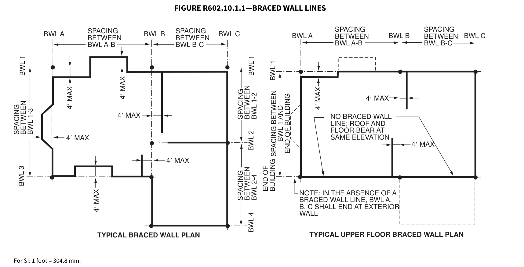
R602.10.1 Braced wall lines. For the purpose of determining the amount and location of bracing required in each story level of a building, braced wall lines shall be designated as straight lines in the building plan placed in accordance with this section.
R602.10.1.1 Length of a braced wall line. The length of a braced wall line shall be the distance between its ends. The end of a braced wall line shall be the intersection with a perpendicular braced wall line, an angled braced wall line as permitted in Section R602.10.1.4 or an exterior wall as shown in Figure R602.10.1.1.
FIGURE R602.10.1.1—BRACED WALL LINES
SPACING
SPACING
SPACING SPACING
SPACING
| BW | WL A BW SPACING BETWEEN | WL B BW SPACING BETWEEN | WL C BWL A BWL B BWL C BETWEEN BETWEEN | WL A BWL BETWEEN | L B BWL BETWEEN | L C | ||||
|---|---|---|---|---|---|---|---|---|---|---|
| BWL A-B | BWL A-B | BWL A-B | BWL A-B | BWL B-C | 4′ MAX 4′ MAX 4′ MAX NOTE: IN THE ABSENCE OF A BRACED WALL LINE, BWL A, B, C SHALL END AT EXTERIOR WALL NO BRACED WALL LINE; ROOF AND FLOOR BEAR AT SAME ELEVATION BWL 1 BWL 1 END OF BUILDING SPACING BETWEEN BWL 1 AND END OF BUILDING BWL 2 WL 4 SPACING BETWEEN BWL 2-4 SPACING BETWEEN BWL 1-2 BWL A-B BWL B-C |
BWL A-B | BWL B-C | BWL B-C | ||
| BWL A-B | BWL A-B | |||||||||
| BWL 1-3 | ||||||||||
| BWL 1-3 | 4′ MAX 4′ MAX NO BRACED WALL LINE; ROOF AND FLOOR BEAR AT SAME ELEVATION |
4′ MAX | 4′ MAX | |||||||
| BWL 1-3 | 4′ MAX | 4′ MAX | 4′ MAX | 4′ MAX | 4′ MAX | 4′ MAX | ||||
| BWL 1-3 | ||||||||||
| 4′ MAX | 4′ MAX | 4′ MAX | 4′ MAX | 4′ MAX | 4′ MAX | 4′ MAX | 4′ MAX | |||
| 4′ MAX | 4′ MAX | 4′ MAX | 4′ MAX | 4′ MAX |
TYPICAL BRACED WALL PLAN TYPICAL UPPER FLOOR BRACED WALL PLAN
For SI: 1 foot = 304.8 mm.
 Open full-size illustration ↗
R602.10.1.2 Location of braced wall lines and permitted offsets.¶
Each braced wall line shall be located such that no more than two-thirds of the required braced wall panel length is located to one side of the braced wall line. Braced wall panels shall be permitted to be offset up to 4 feet (1219 mm) from the designated braced wall line. Braced wall panels parallel to a braced wall line shall be offset not more than 4 feet (1219 mm) from the designated braced wall line location as shown in Figure R602.10.1.1.
Exterior walls parallel to a braced wall line shall be offset not more than 4 feet (1219 mm) from the designated braced wall line location as shown in Figure R602.10.1.1.
Interior walls used as bracing shall be offset not more than 4 feet (1219 mm) from a braced wall line through the interior of the building as shown in Figure R602.10.1.1.
R602.10.1.3 Spacing of braced wall lines.¶
The spacing between parallel braced wall lines shall be in accordance with Table R602.10.1.3. Intermediate braced wall lines through the interior of the building shall be permitted.
TABLE R602.10.1.3—BRACED WALL LINE SPACING
| ** APPLICATION** | ** CONDITION** | ** BUILDING TYPE** | ** BRACED WALL LINE SPACING CRITERIA** | ** BRACED WALL LINE SPACING CRITERIA** |
|---|---|---|---|---|
| ** APPLICATION** | ** CONDITION** | ** BUILDING TYPE** | ** Maximum** Spacing |
** Exception to Maximum Spacing** |
| Wind bracing | Ultimate design wind speed < 140 mph |
Detached, townhouse | 60 feet | None |
| Seismic bracing | SDC A – C | Detached | Use wind bracing | Use wind bracing |
| Seismic bracing | SDC A – B | Townhouse | Use wind bracing | Use wind bracing |
| Seismic bracing | SDC C | Townhouse | 35 feet | Up to 50 feet when length of required bracing per Table R602.10.3(3) is adjusted in accordance with Table R602.10.3(4). |
| Seismic bracing | SDC D0, D1, D2 | Detached, town- houses, one- and two-story only |
25 feet | Up to 35 feet to allow for a single room not to exceed 900 square feet. Spacing of all other braced wall lines shall not exceed 25 feet. |
| Seismic bracing | SDC D0, D1, D2 | Detached, townhouse | 25 feet | Up to 35 feet when length of required bracing per Table R602.10.3(3) is adjusted in accordance with Table R602.10.3(4). |
For SI: 1 foot = 304.8 mm, 1 square foot = 0.0929 m2, 1 mile per hour = 0.447 m/s.
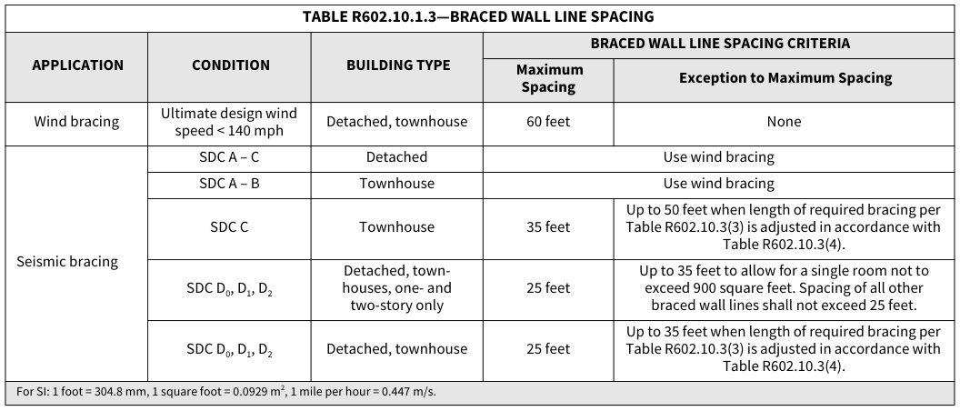 Open full-size table ↗
R602.10.1.4 Angled walls.¶
Any portion of a wall along a braced wall line shall be permitted to angle out of plane for a maximum diagonal length of 8 feet (2438 mm). Where the angled wall occurs at a corner, the length of the braced wall line shall be measured from the projected corner as shown in Figure R602.10.1.4. Where the diagonal length is greater than 8 feet (2438 mm), it shall be considered to be a separate braced wall line and shall be braced in accordance with Section R602.10.1.
FIGURE R602.10.1.4—ANGLED WALLS
PROJECTED CORNER
For SI: 1 foot = 304.8 mm.
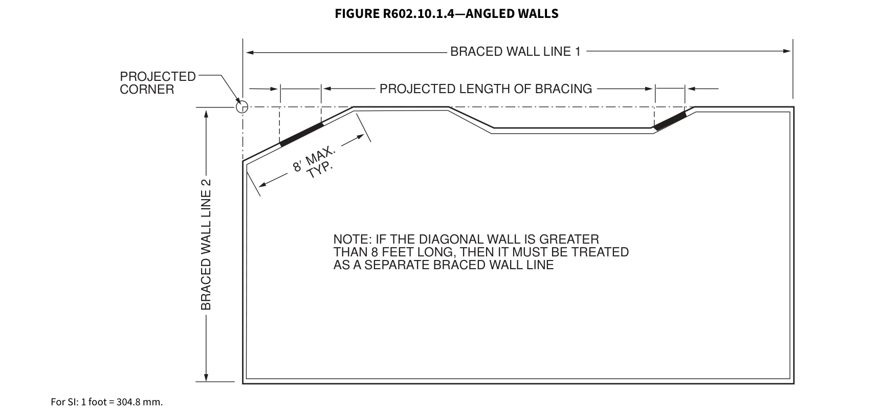 Open full-size illustration ↗
R602.10.2 Braced wall panels.¶
Braced wall panels shall be full-height sections of wall that shall not have vertical or horizontal offsets. Braced wall panels shall be constructed and placed along a braced wall line in accordance with this section and the bracing methods specified in Section R602.10.4.
R602.10.2.1 Braced wall panel uplift load path. The bracing lengths in Table R602.10.3(1) apply only when uplift loads are resisted in accordance with Section R602.3.5.
R602.10.2.2 Locations of braced wall panels. The nearest edge of a braced wall panel shall be located within 10 feet (3810 mm) from each end of a braced wall line as determined in Section R602.10.1.1. The distance between adjacent edges of braced wall panels along a braced wall line shall be not greater than 20 feet (6096 mm) as shown in Figure R602.10.2.2.
Exceptions:
Braced wall panels in Seismic Design Categories D 0, D 1 and D 2 shall comply with Section R602.10.2.2.1.
Braced wall panels with continuous sheathing in Seismic Design Categories A, B and C shall comply with Section R602.10.7.
FIGURE R602.10.2.2—LOCATION OF BRACED WALL PANELS
| BRACED WALL PANEL | BRACED WALL PANEL | |||
|---|---|---|---|---|
| 10' MAX | 20' MAX | 10' MAX | ||
BWL 3 BWL 2 BWL 1
| BRACED WALL PANEL |
||||||||
|---|---|---|---|---|---|---|---|---|
| 20' MAX | ||||||||
| 20' MAX | ||||||||
| 20' MAX | ||||||||
| 20' MAX | ||||||||
| 20' MAX | ||||||||
| 20' MAX | ||||||||
| BRACED WALL PANEL |
BRACED WALL PANEL |
BRACED WALL PANEL |
BRACED WALL PANEL |
BRACED WALL PANEL |
BRACED WALL PANEL |
BRACED WALL PANEL |
| BWL >16' REQUIRES MINIMUM OF 2 BRACED WALL PANELS | 10' MAX | ||
|---|---|---|---|
| BWL >16' REQUIRES MINIMUM OF 2 BRACED WALL PANELS |
10' MAX | BRACED WALL PANEL |
|
| BWL >16' REQUIRES MINIMUM OF 2 BRACED WALL PANELS |
10' MAX | BRACED WALL PANEL |
|
| BWL >16' REQUIRES MINIMUM OF 2 BRACED WALL PANELS |
10' MAX |
| 4' MA | X | |||
|---|---|---|---|---|
| BRACED WALL LINE LOCATIONS AND OFFSETS SHALL COMPLY WITH R602.10.1.2 BRACED WALL PANNEL |
||||
NOTE: CONTINUOUS SHEATHING METHODS REQUIRE ALL FRAMED PORTIONS OF THE BRACED WALL LINE TO BE SHEATHED.
For SI: 1 foot = 304.8 mm.
| 20' MAX | 20' MAX | ||||
|---|---|---|---|---|---|
| 20' MAX | 20' MAX | 20' MAX | 20' MAX | ||
| BRACED WALL PANEL |
BRACED WALL PANEL |
BRACED WALL PANEL |
|||
| BRACED WALL PANEL |
BRACED WALL PANEL |
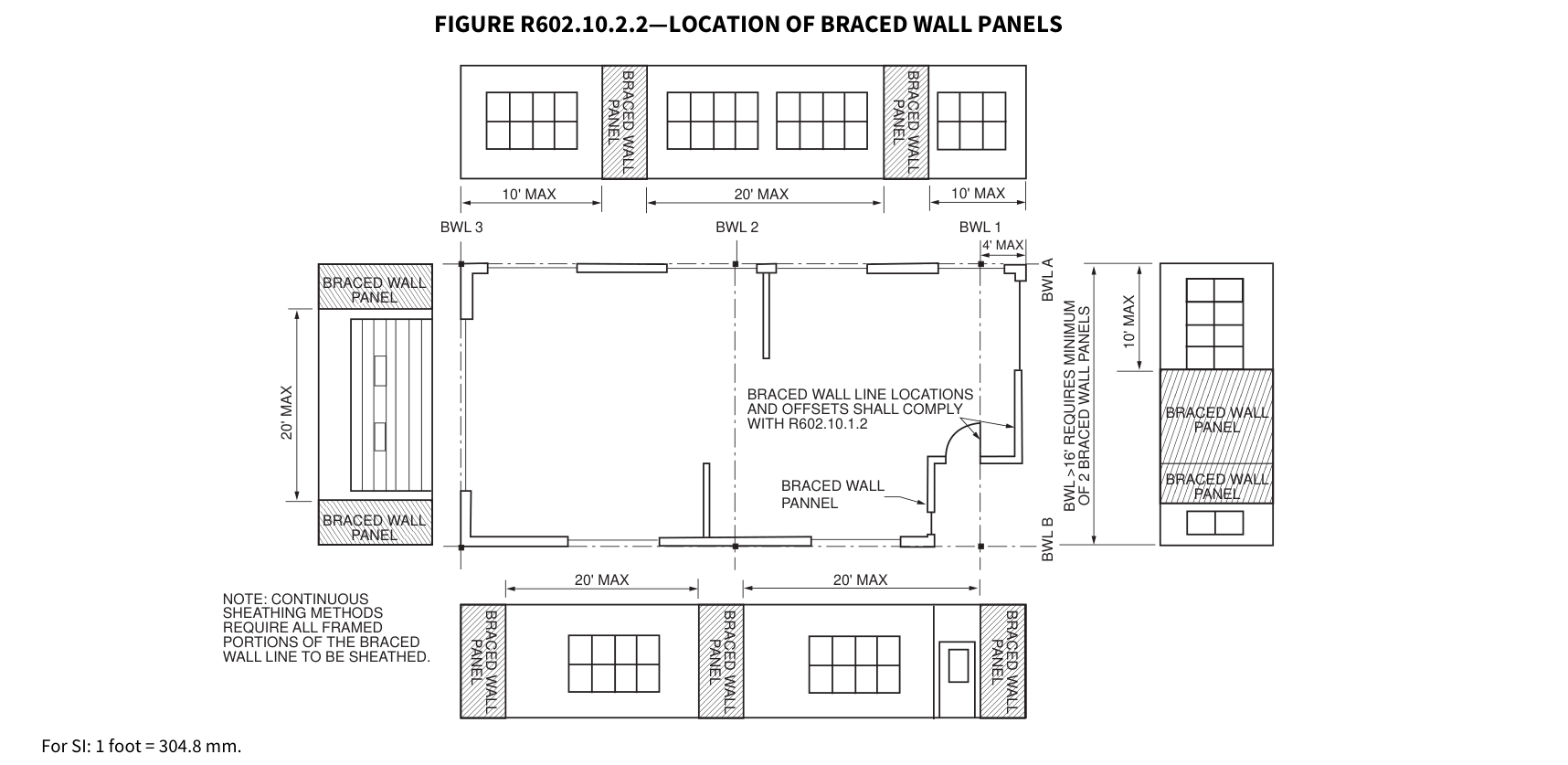 Open full-size illustration ↗
R602.10.2.2.1 Location of braced wall panels in Seismic Design Categories D 0, D 1 and D 2.¶
R602.10.2.2.1 Location of braced wall panels in Seismic Design Categories D 0 , D 1 and D 2 . Braced wall panels shall be located at each end of a braced wall line.
Exceptions:
- Braced wall panels constructed of Method WSP or BV-WSP and continuous sheathing methods as specified in Section R602.10.4 shall be permitted to begin not more than 10 feet (3048 mm) from each end of a braced wall line provided that each end complies with one of the following: 1.1. A minimum 24-inch-wide (610 mm) panel for Methods WSP, CS-WSP, CS-G and CS-PF is applied to each side of the building corner as shown in End Condition 4 of Figure R602.10.7. 1.2. The end of each braced wall panel closest to the end of the braced wall line shall have an 1,800-pound (8 kN) hold-down device fastened to the stud at the edge of the braced wall panel closest to the corner and to the foundation or framing below as shown in End Condition 5 of Figure R602.10.7.
- Braced wall panels constructed of Method PFH or ABW, or of Method BV-WSP where a hold-down is provided in accordance with Table R602.10.6.5.4, shall be permitted to begin not more than 10 feet (3048 mm) from each end of a braced wall line.
R602.10.2.3 Minimum number of braced wall panels.¶
Braced wall lines with a length of 16 feet (4877 mm) or less shall have not less than two braced wall panels of any length or one braced wall panel equal to 48 inches (1219 mm) or more. Braced wall lines greater than 16 feet (4877 mm) shall have not less than two braced wall panels.
R602.10.3 Required length of bracing. The required length of bracing along each braced wall line shall be determined as follows:
- All buildings in Seismic Design Categories A and B shall use Table R602.10.3(1) and the applicable adjustment factors in Table R602.10.3(2).
- Detached buildings in Seismic Design Category C shall use Table R602.10.3(1) and the applicable adjustment factors in Table R602.10.3(2).
- Townhouses in Seismic Design Category C shall use the greater value determined from Table R602.10.3(1) or R602.10.3(3) and the applicable adjustment factors in Table R602.10.3(2) or R602.10.3(4), respectively.
- All buildings in Seismic Design Categories D 0, D 1 and D 2 shall use the greater value determined from Table R602.10.3(1) or R602.10.3(3) and the applicable adjustment factors in Table R602.10.3(2) or R602.10.3(4), respectively.
Only braced wall panels parallel to the braced wall line shall contribute toward the required length of bracing of that braced wall line. Braced wall panels along an angled wall meeting the minimum length requirements of Tables R602.10.5 and R602.10.5.2 shall be permitted to contribute its projected length toward the minimum required length of bracing for the braced wall line as shown in Figure R602.10.1.4. Any braced wall panel on an angled wall at the end of a braced wall line shall contribute its projected length for only one of the braced wall lines at the projected corner.
Exception: The length of wall bracing for dwellings in Seismic Design Categories D 0, D 1 and D 2 with stone or masonry veneer installed in accordance with Section R703.8 and exceeding the first-story height shall be in accordance with Section R602.10.6.5.
TABLE R602.10.3(1)—BRACING REQUIREMENTS BASED ON WIND SPEED¶
TABLE R602.10.3(1)—BRACING REQUIREMENTS BASED ON WIND SPEED
| • EXPOSURE CATEGORY B • 30-FOOT MEAN ROOF HEIGHT • 10-FOOT WALL HEIGHT • 2 BRACED WALL LINES |
• EXPOSURE CATEGORY B • 30-FOOT MEAN ROOF HEIGHT • 10-FOOT WALL HEIGHT • 2 BRACED WALL LINES |
• EXPOSURE CATEGORY B • 30-FOOT MEAN ROOF HEIGHT • 10-FOOT WALL HEIGHT • 2 BRACED WALL LINES |
MINIMUM TOTAL LENGTH (FEET) OF BRACED WALL PANELS REQUIRED ALONG EACH BRACED WALL LINEa |
MINIMUM TOTAL LENGTH (FEET) OF BRACED WALL PANELS REQUIRED ALONG EACH BRACED WALL LINEa |
MINIMUM TOTAL LENGTH (FEET) OF BRACED WALL PANELS REQUIRED ALONG EACH BRACED WALL LINEa |
MINIMUM TOTAL LENGTH (FEET) OF BRACED WALL PANELS REQUIRED ALONG EACH BRACED WALL LINEa |
|---|---|---|---|---|---|---|
| Ultimate Design Wind Speed (mph) |
Story Location | Braced Wall Line Spacingc (feet) |
Method LIBb |
Method GB |
Methods DWB, WSP, SFB, PBS, PCP, HPS, BV-WSP, ABW, PFH, PFG, CS-SFB |
Methods CS-WSP, CS-G, CS-PF |
| < 95 mph | Top story of a one-, two- or three-story building (original diagram) | 10 | 2.5 | 2.5 | 1.5 | 1.5 |
| < 95 mph | Top story of a one-, two- or three-story building (original diagram) | 20 | 4.5 | 4.5 | 2.5 | 2.5 |
| < 95 mph | Top story of a one-, two- or three-story building (original diagram) | 30 | 6.5 | 6.5 | 4.0 | 3.5 |
| < 95 mph | Top story of a one-, two- or three-story building (original diagram) | 40 | 8.5 | 8.5 | 5.0 | 4.0 |
| < 95 mph | Top story of a one-, two- or three-story building (original diagram) | 50 | 10.5 | 10.5 | 6.0 | 5.0 |
| < 95 mph | Top story of a one-, two- or three-story building (original diagram) | 60 | 12.5 | 12.5 | 7.0 | 6.0 |
| < 95 mph | First story of a two-story building or second story of a three-story building (original diagram) | 10 | 5.0 | 5.0 | 3.0 | 2.5 |
| < 95 mph | First story of a two-story building or second story of a three-story building (original diagram) | 20 | 8.5 | 8.5 | 5.0 | 4.5 |
| < 95 mph | First story of a two-story building or second story of a three-story building (original diagram) | 30 | 12.5 | 12.5 | 7.0 | 6.0 |
| < 95 mph | First story of a two-story building or second story of a three-story building (original diagram) | 40 | 16.0 | 16.0 | 9.5 | 8.0 |
| < 95 mph | First story of a two-story building or second story of a three-story building (original diagram) | 50 | 20.0 | 20.0 | 11.5 | 10.0 |
| < 95 mph | First story of a two-story building or second story of a three-story building (original diagram) | 60 | 23.5 | 23.5 | 13.5 | 11.5 |
| < 95 mph | First story of a three-story building (original diagram) | 10 | NP | 7.0 | 4.0 | 3.5 |
| < 95 mph | First story of a three-story building (original diagram) | 20 | NP | 13.0 | 7.5 | 6.5 |
| < 95 mph | First story of a three-story building (original diagram) | 30 | NP | 18.5 | 10.5 | 9.0 |
| < 95 mph | First story of a three-story building (original diagram) | 40 | NP | 24.0 | 13.5 | 11.5 |
| < 95 mph | First story of a three-story building (original diagram) | 50 | NP | 29.5 | 17.0 | 14.5 |
| < 95 mph | First story of a three-story building (original diagram) | 60 | NP | 35.0 | 20.0 | 17.0 |
| ≤ 110 | Top story of a one-, two- or three-story building (original diagram) | 10 | 3.5 | 3.5 | 2.0 | 1.5 |
| ≤ 110 | Top story of a one-, two- or three-story building (original diagram) | 20 | 6.0 | 6.0 | 3.5 | 3.0 |
| ≤ 110 | Top story of a one-, two- or three-story building (original diagram) | 30 | 8.5 | 8.5 | 5.0 | 4.5 |
| ≤ 110 | Top story of a one-, two- or three-story building (original diagram) | 40 | 11.5 | 11.5 | 6.5 | 5.5 |
| ≤ 110 | Top story of a one-, two- or three-story building (original diagram) | 50 | 14.0 | 14.0 | 8.0 | 7.0 |
| ≤ 110 | Top story of a one-, two- or three-story building (original diagram) | 60 | 16.5 | 16.5 | 9.5 | 8.0 |
| ≤ 110 | First story of a two-story building or second story of a three-story building (original diagram) | 10 | 6.5 | 6.5 | 3.5 | 3.0 |
| ≤ 110 | First story of a two-story building or second story of a three-story building (original diagram) | 20 | 11.5 | 11.5 | 6.5 | 5.5 |
| ≤ 110 | First story of a two-story building or second story of a three-story building (original diagram) | 30 | 16.5 | 16.5 | 9.5 | 8.0 |
| ≤ 110 | First story of a two-story building or second story of a three-story building (original diagram) | 40 | 21.5 | 21.5 | 12.5 | 10.5 |
| ≤ 110 | First story of a two-story building or second story of a three-story building (original diagram) | 50 | 26.5 | 26.5 | 15.5 | 13.0 |
| ≤ 110 | First story of a two-story building or second story of a three-story building (original diagram) | 60 | 31.5 | 31.5 | 18.0 | 15.5 |
| ≤ 110 | First story of a three-story building (original diagram) | 10 | NP | 9.5 | 5.5 | 4.5 |
TABLE R602.10.3(1)—BRACING REQUIREMENTS BASED ON WIND SPEED
| ≤ 110 | First story of a three-story building (original diagram) | 20 | NP | 17.0 | 10.0 | 8.5 |
|---|---|---|---|---|---|---|
| ≤ 110 | First story of a three-story building (original diagram) | 30 | NP | 24.5 | 14.0 | 12.0 |
| ≤ 110 | First story of a three-story building (original diagram) | 40 | NP | 32.0 | 18.5 | 15.5 |
| ≤ 110 | First story of a three-story building (original diagram) | 50 | NP | 39.5 | 22.5 | 19.0 |
| ≤ 110 | First story of a three-story building (original diagram) | 60 | NP | 46.5 | 26.5 | 23.0 |
TABLE R602.10.3(1)—BRACING REQUIREMENTS BASED ON WIND SPEED—continued
| • EXPOSURE CATEGORY B • 30-FOOT MEAN ROOF HEIGHT • 10-FOOT WALL HEIGHT • 2 BRACED WALL LINES |
• EXPOSURE CATEGORY B • 30-FOOT MEAN ROOF HEIGHT • 10-FOOT WALL HEIGHT • 2 BRACED WALL LINES |
• EXPOSURE CATEGORY B • 30-FOOT MEAN ROOF HEIGHT • 10-FOOT WALL HEIGHT • 2 BRACED WALL LINES |
MINIMUM TOTAL LENGTH (FEET) OF BRACED WALL PANELS REQUIRED ALONG EACH BRACED WALL LINEa |
MINIMUM TOTAL LENGTH (FEET) OF BRACED WALL PANELS REQUIRED ALONG EACH BRACED WALL LINEa |
MINIMUM TOTAL LENGTH (FEET) OF BRACED WALL PANELS REQUIRED ALONG EACH BRACED WALL LINEa |
MINIMUM TOTAL LENGTH (FEET) OF BRACED WALL PANELS REQUIRED ALONG EACH BRACED WALL LINEa |
|---|---|---|---|---|---|---|
| Ultimate Design Wind Speed (mph) |
Story Location | Braced Wall Line Spacingc (feet) |
Method LIBb |
Method GB |
Methods DWB, WSP, SFB, PBS, PCP, HPS, BV-WSP, ABW, PFH, PFG, CS-SFB |
Methods CS-WSP, CS-G, CS-PF |
| ≤ 115 | Top story of a one-, two- or three-story building (original diagram) | 10 | 3.5 | 3.5 | 2.0 | 2.0 |
| ≤ 115 | Top story of a one-, two- or three-story building (original diagram) | 20 | 6.5 | 6.5 | 3.5 | 3.5 |
| ≤ 115 | Top story of a one-, two- or three-story building (original diagram) | 30 | 9.5 | 9.5 | 5.5 | 4.5 |
| ≤ 115 | Top story of a one-, two- or three-story building (original diagram) | 40 | 12.5 | 12.5 | 7.0 | 6.0 |
| ≤ 115 | Top story of a one-, two- or three-story building (original diagram) | 50 | 15.0 | 15.0 | 9.0 | 7.5 |
| ≤ 115 | Top story of a one-, two- or three-story building (original diagram) | 60 | 18.0 | 18.0 | 10.5 | 9.0 |
| ≤ 115 | First story of a two-story building or second story of a three-story building (original diagram) | 10 | 7.0 | 7.0 | 4.0 | 3.5 |
| ≤ 115 | First story of a two-story building or second story of a three-story building (original diagram) | 20 | 12.5 | 12.5 | 7.5 | 6.5 |
| ≤ 115 | First story of a two-story building or second story of a three-story building (original diagram) | 30 | 18.0 | 18.0 | 10.5 | 9.0 |
| ≤ 115 | First story of a two-story building or second story of a three-story building (original diagram) | 40 | 23.5 | 23.5 | 13.5 | 11.5 |
| ≤ 115 | First story of a two-story building or second story of a three-story building (original diagram) | 50 | 29.0 | 29.0 | 16.5 | 14.0 |
| ≤ 115 | First story of a two-story building or second story of a three-story building (original diagram) | 60 | 34.5 | 34.5 | 20.0 | 17.0 |
| ≤ 115 | First story of a three-story building (original diagram) | 10 | NP | 10.0 | 6.0 | 5.0 |
| ≤ 115 | First story of a three-story building (original diagram) | 20 | NP | 18.5 | 11.0 | 9.0 |
| ≤ 115 | First story of a three-story building (original diagram) | 30 | NP | 27.0 | 15.5 | 13.0 |
| ≤ 115 | First story of a three-story building (original diagram) | 40 | NP | 35.0 | 20.0 | 17.0 |
| ≤ 115 | First story of a three-story building (original diagram) | 50 | NP | 43.0 | 24.5 | 21.0 |
| ≤ 115 | First story of a three-story building (original diagram) | 60 | NP | 51.0 | 29.0 | 25.0 |
| ≤ 120 | Top story of a one-, two- or three-story building (original diagram) | 10 | 4.0 | 4.0 | 2.5 | 2.0 |
| ≤ 120 | Top story of a one-, two- or three-story building (original diagram) | 20 | 7.0 | 7.0 | 4.0 | 3.5 |
| ≤ 120 | Top story of a one-, two- or three-story building (original diagram) | 30 | 10.5 | 10.5 | 6.0 | 5.0 |
| ≤ 120 | Top story of a one-, two- or three-story building (original diagram) | 40 | 13.5 | 13.5 | 8.0 | 6.5 |
| ≤ 120 | Top story of a one-, two- or three-story building (original diagram) | 50 | 16.5 | 16.5 | 9.5 | 8.0 |
| ≤ 120 | Top story of a one-, two- or three-story building (original diagram) | 60 | 19.5 | 19.5 | 11.5 | 9.5 |
| ≤ 120 | First story of a two-story building or second story of a three-story building (original diagram) | 10 | 7.5 | 7.5 | 4.5 | 3.5 |
| ≤ 120 | First story of a two-story building or second story of a three-story building (original diagram) | 20 | 14.0 | 14.0 | 8.0 | 7.0 |
TABLE R602.10.3(1)—BRACING REQUIREMENTS BASED ON WIND SPEED
| ≤ 120 | First story of a two-story building or second story of a three-story building (original diagram) | 30 | 20.0 | 20.0 | 11.5 | 9.5 |
|---|---|---|---|---|---|---|
| ≤ 120 | First story of a two-story building or second story of a three-story building (original diagram) | 40 | 25.5 | 25.5 | 15.0 | 12.5 |
| ≤ 120 | First story of a two-story building or second story of a three-story building (original diagram) | 50 | 31.5 | 31.5 | 18.0 | 15.5 |
| ≤ 120 | First story of a two-story building or second story of a three-story building (original diagram) | 60 | 37.5 | 37.5 | 21.5 | 18.5 |
| ≤ 120 | First story of a three-story building (original diagram) | 10 | NP | 11.0 | 6.5 | 5.5 |
| ≤ 120 | First story of a three-story building (original diagram) | 20 | NP | 20.5 | 11.5 | 10.0 |
| ≤ 120 | First story of a three-story building (original diagram) | 30 | NP | 29.0 | 17.0 | 14.5 |
| ≤ 120 | First story of a three-story building (original diagram) | 40 | NP | 38.0 | 22.0 | 18.5 |
| ≤ 120 | First story of a three-story building (original diagram) | 50 | NP | 47.0 | 27.0 | 23.0 |
| ≤ 120 | First story of a three-story building (original diagram) | 60 | NP | 55.5 | 32.0 | 27.0 |
TABLE R602.10.3(1)—BRACING REQUIREMENTS BASED ON WIND SPEED—continued
| • EXPOSURE CATEGORY B • 30-FOOT MEAN ROOF HEIGHT • 10-FOOT WALL HEIGHT • 2 BRACED WALL LINES |
• EXPOSURE CATEGORY B • 30-FOOT MEAN ROOF HEIGHT • 10-FOOT WALL HEIGHT • 2 BRACED WALL LINES |
• EXPOSURE CATEGORY B • 30-FOOT MEAN ROOF HEIGHT • 10-FOOT WALL HEIGHT • 2 BRACED WALL LINES |
MINIMUM TOTAL LENGTH (FEET) OF BRACED WALL PANELS REQUIRED ALONG EACH BRACED WALL LINEa |
MINIMUM TOTAL LENGTH (FEET) OF BRACED WALL PANELS REQUIRED ALONG EACH BRACED WALL LINEa |
MINIMUM TOTAL LENGTH (FEET) OF BRACED WALL PANELS REQUIRED ALONG EACH BRACED WALL LINEa |
MINIMUM TOTAL LENGTH (FEET) OF BRACED WALL PANELS REQUIRED ALONG EACH BRACED WALL LINEa |
|---|---|---|---|---|---|---|
| Ultimate Design Wind Speed (mph) |
Story Location | Braced Wall Line Spacingc (feet) |
Method LIBb |
Method GB |
Methods DWB, WSP, SFB, PBS, PCP, HPS, BV-WSP, ABW, PFH, PFG, CS-SFB |
Methods CS-WSP, CS-G, CS-PF |
| ≤ 130 | Top story of a one-, two- or three-story building (original diagram) | 10 | 4.5 | 4.5 | 2.5 | 2.5 |
| ≤ 130 | Top story of a one-, two- or three-story building (original diagram) | 20 | 8.5 | 8.5 | 5.0 | 4.0 |
| ≤ 130 | Top story of a one-, two- or three-story building (original diagram) | 30 | 12.0 | 12.0 | 7.0 | 6.0 |
| ≤ 130 | Top story of a one-, two- or three-story building (original diagram) | 40 | 15.5 | 15.5 | 9.0 | 7.5 |
| ≤ 130 | Top story of a one-, two- or three-story building (original diagram) | 50 | 19.5 | 19.5 | 11.0 | 9.5 |
| ≤ 130 | Top story of a one-, two- or three-story building (original diagram) | 60 | 23.0 | 23.0 | 13.0 | 11.0 |
| ≤ 130 | First story of a two-story building or second story of a three-story building (original diagram) | 10 | 8.5 | 8.5 | 5.0 | 4.5 |
| ≤ 130 | First story of a two-story building or second story of a three-story building (original diagram) | 20 | 16.0 | 16.0 | 9.5 | 8.0 |
| ≤ 130 | First story of a two-story building or second story of a three-story building (original diagram) | 30 | 23.0 | 23.0 | 13.5 | 11.5 |
| ≤ 130 | First story of a two-story building or second story of a three-story building (original diagram) | 40 | 30.0 | 30.0 | 17.5 | 15.0 |
| ≤ 130 | First story of a two-story building or second story of a three-story building (original diagram) | 50 | 37.0 | 37.0 | 21.5 | 18.0 |
| ≤ 130 | First story of a two-story building or second story of a three-story building (original diagram) | 60 | 44.0 | 44.0 | 25.0 | 21.5 |
| ≤ 130 | First story of a three-story building (original diagram) | 10 | NP | 13.0 | 7.5 | 6.5 |
| ≤ 130 | First story of a three-story building (original diagram) | 20 | NP | 24.0 | 13.5 | 11.5 |
| ≤ 130 | First story of a three-story building (original diagram) | 30 | NP | 34.5 | 19.5 | 17.0 |
| ≤ 130 | First story of a three-story building (original diagram) | 40 | NP | 44.5 | 25.5 | 22.0 |
| ≤ 130 | First story of a three-story building (original diagram) | 50 | NP | 55.0 | 31.5 | 26.5 |
| ≤ 130 | First story of a three-story building (original diagram) | 60 | NP | 65.0 | 37.5 | 31.5 |
| < 140 | Top story of a one-, two- or three-story building (original diagram) | 10 | 5.5 | 5.5 | 3.0 | 2.5 |
| < 140 | Top story of a one-, two- or three-story building (original diagram) | 20 | 10.0 | 10.0 | 5.5 | 5.0 |
| < 140 | Top story of a one-, two- or three-story building (original diagram) | 30 | 14.0 | 14.0 | 8.0 | 7.0 |
TABLE R602.10.3(1)—BRACING REQUIREMENTS BASED ON WIND SPEED
| < 140 | Top story of a one-, two- or three-story building (original diagram) | 40 | 18.0 | 18.0 | 10.5 | 9.0 |
|---|---|---|---|---|---|---|
| < 140 | Top story of a one-, two- or three-story building (original diagram) | 50 | 22.5 | 22.5 | 13.0 | 11.0 |
| < 140 | Top story of a one-, two- or three-story building (original diagram) | 60 | 26.5 | 26.5 | 15.0 | 13.0 |
| < 140 | First story of a two-story building or second story of a three-story building (original diagram) | 10 | 10.0 | 10.0 | 6.0 | 5.0 |
| < 140 | First story of a two-story building or second story of a three-story building (original diagram) | 20 | 18.5 | 18.5 | 11.0 | 9.0 |
| < 140 | First story of a two-story building or second story of a three-story building (original diagram) | 30 | 27.0 | 27.0 | 15.5 | 13.0 |
| < 140 | First story of a two-story building or second story of a three-story building (original diagram) | 40 | 35.0 | 35.0 | 20.0 | 17.0 |
| < 140 | First story of a two-story building or second story of a three-story building (original diagram) | 50 | 43.0 | 43.0 | 24.5 | 21.0 |
| < 140 | First story of a two-story building or second story of a three-story building (original diagram) | 60 | 51.0 | 51.0 | 29.0 | 25.0 |
| < 140 | First story of a three-story building (original diagram) | 10 | NP | 15.0 | 8.5 | 7.5 |
| < 140 | First story of a three-story building (original diagram) | 20 | NP | 27.5 | 16.0 | 13.5 |
| < 140 | First story of a three-story building (original diagram) | 30 | NP | 39.5 | 23.0 | 19.5 |
| < 140 | First story of a three-story building (original diagram) | 40 | NP | 51.5 | 29.5 | 25.0 |
| < 140 | First story of a three-story building (original diagram) | 50 | NP | 63.5 | 36.5 | 31.0 |
| < 140 | First story of a three-story building (original diagram) | 60 | NP | 75.5 | 43.0 | 36.5 |
For SI: 1 inch = 25.4 mm, 1 foot = 304.8 mm, 1 mile per hour = 0.447 m/s. NP = Not Permitted. a. Linear interpolation shall be permitted. b. Method LIB shall have gypsum board fastened to not less than one side with nails or screws in accordance with Table R602.3(1) for exterior sheathing or Table R702.3.5 for interior gypsum board. Spacing of fasteners at panel edges shall not exceed 8 inches. c. Where three or more parallel braced wall lines are present and the distances between adjacent braced wall lines are different, the average dimension shall be permitted to be used for braced wall line spacing.
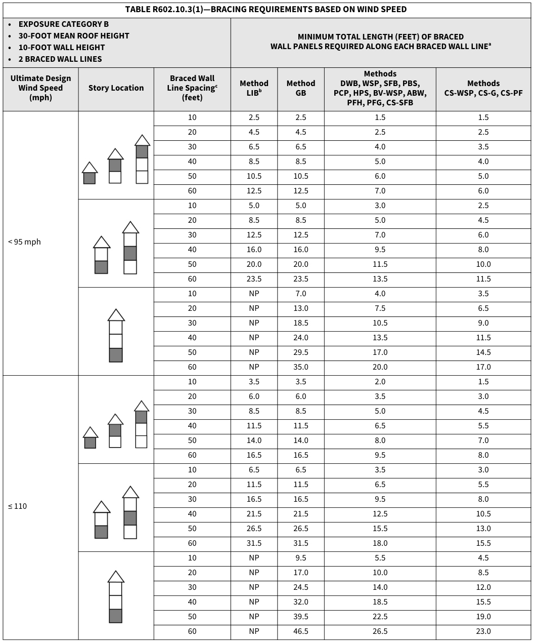 Open full-size table ↗
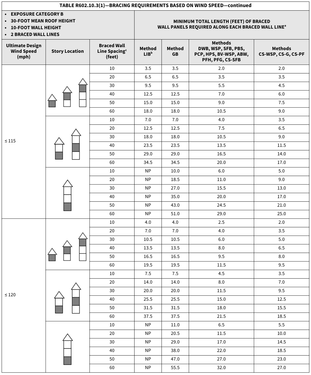 Open full-size table ↗
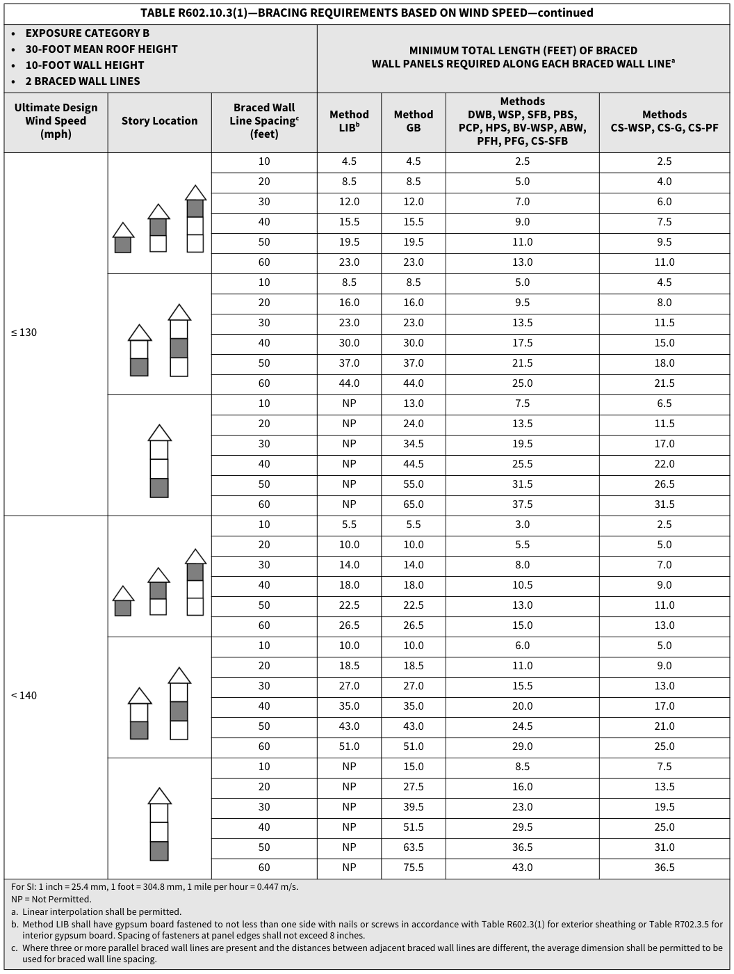 Open full-size table ↗
TABLE R602.10.3(2)—WIND ADJUSTMENT FACTORS TO THE REQUIRED LENGTH OF WALL BRACING¶
TABLE R602.10.3(2)—WIND ADJUSTMENT FACTORS TO THE REQUIRED LENGTH OF WALL BRACING
| ** ITEM** NUMBER |
** ADJUSTMENT** BASED ON |
** STORY/ |
** CONDITION** | ** ADJUSTMENT FACTORa, b [multiply length from** Table R602.10.3(1) by this factor] |
** APPLICABLE** METHODS |
|---|---|---|---|---|---|
| 1 | Exposure categoryd | One-story structure | B | 1.00 | All methods |
| 1 | Exposure categoryd | One-story structure | C | 1.20 | All methods |
| 1 | Exposure categoryd | One-story structure | D | 1.50 | All methods |
| 1 | Exposure categoryd | Two-story structure | B | 1.00 | All methods |
| 1 | Exposure categoryd | Two-story structure | C | 1.30 | All methods |
| 1 | Exposure categoryd | Two-story structure | D | 1.60 | All methods |
| 1 | Exposure categoryd | Three-story structure | B | 1.00 | All methods |
| 1 | Exposure categoryd | Three-story structure | C | 1.40 | All methods |
| 1 | Exposure categoryd | Three-story structure | D | 1.70 | All methods |
| 2 | Roof eave-to-ridge height | Roof only | ≤ 5 feet | 0.70 | All methods |
| 2 | Roof eave-to-ridge height | Roof only | 10 feet | 1.00 | All methods |
| 2 | Roof eave-to-ridge height | Roof only | 15 feet | 1.30 | All methods |
| 2 | Roof eave-to-ridge height | Roof only | 20 feet | 1.60 | All methods |
| 2 | Roof eave-to-ridge height | Roof + 1 floor | ≤ 5 feet | 0.85 | All methods |
| 2 | Roof eave-to-ridge height | Roof + 1 floor | 10 feet | 1.00 | All methods |
| 2 | Roof eave-to-ridge height | Roof + 1 floor | 15 feet | 1.15 | All methods |
| 2 | Roof eave-to-ridge height | Roof + 1 floor | 20 feet | 1.30 | All methods |
| 2 | Roof eave-to-ridge height | Roof + 2 floors | ≤ 5 feet | 0.90 | All methods |
| 2 | Roof eave-to-ridge height | Roof + 2 floors | 10 feet | 1.00 | All methods |
| 2 | Roof eave-to-ridge height | Roof + 2 floors | 15 feet | 1.10 | All methods |
| 2 | Roof eave-to-ridge height | Roof + 2 floors | 20 feet | Not permitted | All methods |
| 3 | Wall Height (Section R602.10.3.1) |
Any story | 8 feet | 0.90 | All methods |
| 3 | Wall Height (Section R602.10.3.1) |
Any story | 9 feet | 0.95 | All methods |
| 3 | Wall Height (Section R602.10.3.1) |
Any story | 10 feet | 1.00 | All methods |
| 3 | Wall Height (Section R602.10.3.1) |
Any story | 11 feet | 1.05 | All methods |
| 3 | Wall Height (Section R602.10.3.1) |
Any story | 12 feet | 1.10 | All methods |
| 4 | Number of braced wall lines (per plan direction)c |
Any story | 2 | 1.00 | All methods |
| 4 | Number of braced wall lines (per plan direction)c |
Any story | 3 | 1.30 | All methods |
| 4 | Number of braced wall lines (per plan direction)c |
Any story | 4 | 1.45 | All methods |
| 4 | Number of braced wall lines (per plan direction)c |
Any story | ≥ 5 | 1.60 | All methods |
| 5 | Additional 800-pound hold-down device |
Top story only | Fastened to the end studs of each braced wall panel and to the foundation or framing below |
0.80 | DWB, WSP, SFB, PBS, PCP, HPS |
| 6 | Interior gypsum board finish (or equivalent) |
Any story | Omitted from inside face of braced wall panels |
1.40 | DWB, WSP, SFB, PBS, PCP, HPS, CS-WSP, CS-G, CS-SFB |
| 7 | Gypsum board fastening | Any story | 4 inches o.c. at panel edges, including top and bottom plates, and all horizontal joints blocked |
0.7 | GB |
| 8 | Horizontal blocking | Any story | Horizontal block is omitted |
2.0 | WSP, PBS, CS-WSP |
For SI: 1 inch = 25.4 mm, 1 foot = 304.8 mm, 1 pound = 4.48 N. a. Linear interpolation shall be permitted. b. The total adjustment factor is the product of all applicable adjustment factors. c. The adjustment factor is permitted to be 1.0 when determining bracing amounts for intermediate braced wall lines provided the bracing amounts on adjacent braced wall lines are based on a spacing and number that neglects the intermediate braced wall line. d. The same adjustment factor shall be applied to all braced wall lines on all floors of the structure, based on the worst-case exposure category.
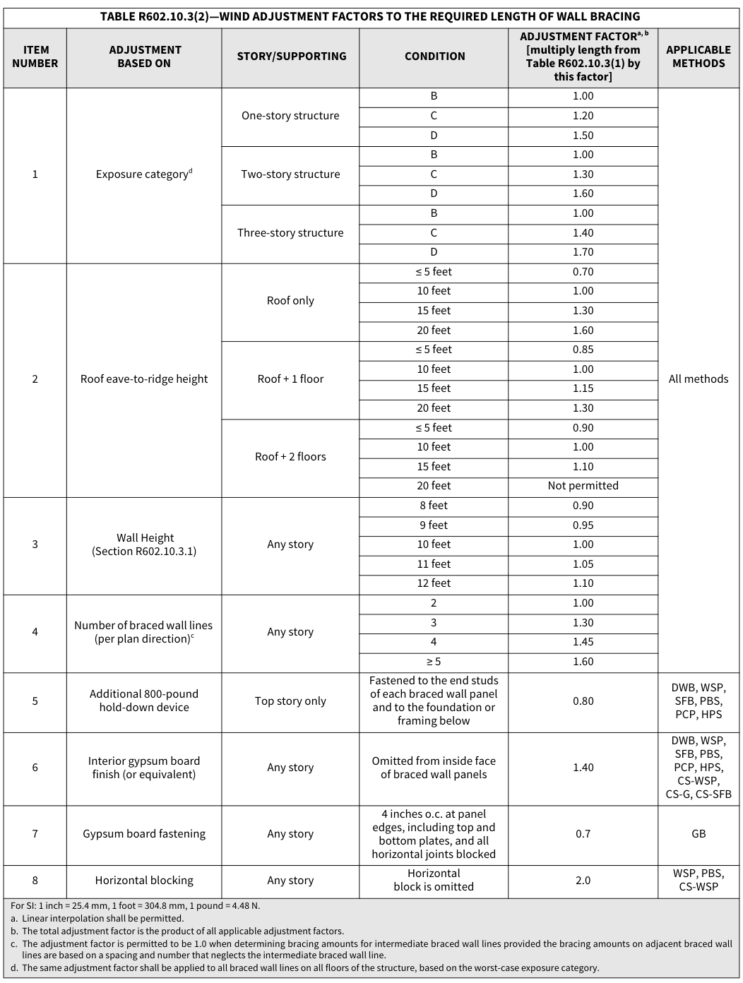 Open full-size table ↗
TABLE R602.10.3(3)—BRACING REQUIREMENTS BASED ON SEISMIC DESIGN CATEGORY¶
TABLE R602.10.3(3)—BRACING REQUIREMENTS BASED ON SEISMIC DESIGN CATEGORY
| • WALL HEIGHT = 10 FEET • 10 PSF FLOOR DEAD LOAD • 15 PSF ROOF/ • BRACED WALL LINE SPACING ≤ 25 FEET |
• WALL HEIGHT = 10 FEET • 10 PSF FLOOR DEAD LOAD • 15 PSF ROOF/ • BRACED WALL LINE SPACING ≤ 25 FEET |
• WALL HEIGHT = 10 FEET • 10 PSF FLOOR DEAD LOAD • 15 PSF ROOF/ • BRACED WALL LINE SPACING ≤ 25 FEET |
** MINIMUM TOTAL LENGTH (FEET) OF BRACED** WALL PANELS REQUIRED ALONG EACH BRACED WALL LINEa, g |
** MINIMUM TOTAL LENGTH (FEET) OF BRACED** WALL PANELS REQUIRED ALONG EACH BRACED WALL LINEa, g |
** MINIMUM TOTAL LENGTH (FEET) OF BRACED** WALL PANELS REQUIRED ALONG EACH BRACED WALL LINEa, g |
** MINIMUM TOTAL LENGTH (FEET) OF BRACED** WALL PANELS REQUIRED ALONG EACH BRACED WALL LINEa, g |
** MINIMUM TOTAL LENGTH (FEET) OF BRACED** WALL PANELS REQUIRED ALONG EACH BRACED WALL LINEa, g |
|---|---|---|---|---|---|---|---|
| ** Seismic Design** Categoryb |
** Story Location** | ** Braced Wall Line** Length (feet)c |
** Method** LIBd |
** Method** GB |
** Methods DWB,** SFB, PBS, PCP, HPS, CS-SFBe |
** Methods WSP,** **ABWf, PFHf ** and PFGe, f |
** Methods** CS-WSP, CS-G, CS-PF |
| C (townhouses only) |
Top story of a one-, two- or three-story building (original diagram) | 10 | 2.5 | 2.5 | 2.5 | 1.6 | 1.4 |
| C (townhouses only) |
Top story of a one-, two- or three-story building (original diagram) | 20 | 5.0 | 5.0 | 5.0 | 3.2 | 2.7 |
| C (townhouses only) |
Top story of a one-, two- or three-story building (original diagram) | 30 | 7.5 | 7.5 | 7.5 | 4.8 | 4.1 |
| C (townhouses only) |
Top story of a one-, two- or three-story building (original diagram) | 40 | 10.0 | 10.0 | 10.0 | 6.4 | 5.4 |
| C (townhouses only) |
Top story of a one-, two- or three-story building (original diagram) | 50 | 12.5 | 12.5 | 12.5 | 8.0 | 6.8 |
| C (townhouses only) |
First story of a two-story building or second story of a three-story building (original diagram) | 10 | NP | 4.5 | 4.5 | 3.0 | 2.6 |
| C (townhouses only) |
First story of a two-story building or second story of a three-story building (original diagram) | 20 | NP | 9.0 | 9.0 | 6.0 | 5.1 |
| C (townhouses only) |
First story of a two-story building or second story of a three-story building (original diagram) | 30 | NP | 13.5 | 13.5 | 9.0 | 7.7 |
| C (townhouses only) |
First story of a two-story building or second story of a three-story building (original diagram) | 40 | NP | 18.0 | 18.0 | 12.0 | 10.2 |
| C (townhouses only) |
First story of a two-story building or second story of a three-story building (original diagram) | 50 | NP | 22.5 | 22.5 | 15.0 | 12.8 |
| C (townhouses only) |
First story of a three-story building (original diagram) | 10 | NP | 6.0 | 6.0 | 4.5 | 3.8 |
| C (townhouses only) |
First story of a three-story building (original diagram) | 20 | NP | 12.0 | 12.0 | 9.0 | 7.7 |
| C (townhouses only) |
First story of a three-story building (original diagram) | 30 | NP | 18.0 | 18.0 | 13.5 | 11.5 |
| C (townhouses only) |
First story of a three-story building (original diagram) | 40 | NP | 24.0 | 24.0 | 18.0 | 15.3 |
| C (townhouses only) |
First story of a three-story building (original diagram) | 50 | NP | 30.0 | 30.0 | 22.5 | 19.1 |
| D0 | Top story of a one-, two- or three-story building (original diagram) | 10 | NP | 2.8 | 2.8 | 1.8 | 1.6 |
| D0 | Top story of a one-, two- or three-story building (original diagram) | 20 | NP | 5.5 | 5.5 | 3.6 | 3.1 |
| D0 | Top story of a one-, two- or three-story building (original diagram) | 30 | NP | 8.3 | 8.3 | 5.4 | 4.6 |
| D0 | Top story of a one-, two- or three-story building (original diagram) | 40 | NP | 11.0 | 11.0 | 7.2 | 6.1 |
| D0 | Top story of a one-, two- or three-story building (original diagram) | 50 | NP | 13.8 | 13.8 | 9.0 | 7.7 |
| D0 | First story of a two-story building or second story of a three-story building (original diagram) | 10 | NP | 5.3 | 5.3 | 3.8 | 3.2 |
| D0 | First story of a two-story building or second story of a three-story building (original diagram) | 20 | NP | 10.5 | 10.5 | 7.5 | 6.4 |
| D0 | First story of a two-story building or second story of a three-story building (original diagram) | 30 | NP | 15.8 | 15.8 | 11.3 | 9.6 |
| D0 | First story of a two-story building or second story of a three-story building (original diagram) | 40 | NP | 21.0 | 21.0 | 15.0 | 12.8 |
| D0 | First story of a two-story building or second story of a three-story building (original diagram) | 50 | NP | 26.3 | 26.3 | 18.8 | 16.0 |
| D0 | First story of a three-story building (original diagram) | 10 | NP | 7.3 | 7.3 | 5.3 | 4.5 |
| D0 | First story of a three-story building (original diagram) | 20 | NP | 14.5 | 14.5 | 10.5 | 9.0 |
TABLE R602.10.3(3)—BRACING REQUIREMENTS BASED ON SEISMIC DESIGN CATEGORY
| D0 | First story of a three-story building (original diagram) | 30 | NP | 21.8 | 21.8 | 15.8 | 13.4 |
|---|---|---|---|---|---|---|---|
| D0 | First story of a three-story building (original diagram) | 40 | NP | 29.0 | 29.0 | 21.0 | 17.9 |
| D0 | First story of a three-story building (original diagram) | 50 | NP | 36.3 | 36.3 | 26.3 | 22.3 |
TABLE R602.10.3(3)—BRACING REQUIREMENTS BASED ON SEISMIC DESIGN CATEGORY—continued
| • WALL HEIGHT = 10 FEET • 10 PSF FLOOR DEAD LOAD • 15 PSF ROOF/ • BRACED WALL LINE SPACING ≤ 25 FEET |
• WALL HEIGHT = 10 FEET • 10 PSF FLOOR DEAD LOAD • 15 PSF ROOF/ • BRACED WALL LINE SPACING ≤ 25 FEET |
• WALL HEIGHT = 10 FEET • 10 PSF FLOOR DEAD LOAD • 15 PSF ROOF/ • BRACED WALL LINE SPACING ≤ 25 FEET |
** MINIMUM TOTAL LENGTH (FEET) OF BRACED** WALL PANELS REQUIRED ALONG EACH BRACED WALL LINEa, g |
** MINIMUM TOTAL LENGTH (FEET) OF BRACED** WALL PANELS REQUIRED ALONG EACH BRACED WALL LINEa, g |
** MINIMUM TOTAL LENGTH (FEET) OF BRACED** WALL PANELS REQUIRED ALONG EACH BRACED WALL LINEa, g |
** MINIMUM TOTAL LENGTH (FEET) OF BRACED** WALL PANELS REQUIRED ALONG EACH BRACED WALL LINEa, g |
** MINIMUM TOTAL LENGTH (FEET) OF BRACED** WALL PANELS REQUIRED ALONG EACH BRACED WALL LINEa, g |
|---|---|---|---|---|---|---|---|
| ** Seismic Design** Categoryb |
** Story Location** | ** Braced Wall Line** Length (feet)c |
** Method** LIBd |
** Method** GB |
** Methods DWB,** SFB, PBS, PCP, HPS, CS-SFBe |
** Methods WSP,** **ABWf, PFHf ** and PFGe, f |
** Methods** CS-WSP, CS-G, CS-PF |
| D1 | Top story of a one-, two- or three-story building (original diagram) | 10 | NP | 3.0 | 3.0 | 2.0 | 1.7 |
| D1 | Top story of a one-, two- or three-story building (original diagram) | 20 | NP | 6.0 | 6.0 | 4.0 | 3.4 |
| D1 | Top story of a one-, two- or three-story building (original diagram) | 30 | NP | 9.0 | 9.0 | 6.0 | 5.1 |
| D1 | Top story of a one-, two- or three-story building (original diagram) | 40 | NP | 12.0 | 12.0 | 8.0 | 6.8 |
| D1 | Top story of a one-, two- or three-story building (original diagram) | 50 | NP | 15.0 | 15.0 | 10.0 | 8.5 |
| D1 | First story of a two-story building or second story of a three-story building (original diagram) | 10 | NP | 6.0 | 6.0 | 4.5 | 3.8 |
| D1 | First story of a two-story building or second story of a three-story building (original diagram) | 20 | NP | 12.0 | 12.0 | 9.0 | 7.7 |
| D1 | First story of a two-story building or second story of a three-story building (original diagram) | 30 | NP | 18.0 | 18.0 | 13.5 | 11.5 |
| D1 | First story of a two-story building or second story of a three-story building (original diagram) | 40 | NP | 24.0 | 24.0 | 18.0 | 15.3 |
| D1 | First story of a two-story building or second story of a three-story building (original diagram) | 50 | NP | 30.0 | 30.0 | 22.5 | 19.1 |
| D1 | First story of a three-story building (original diagram) | 10 | NP | 8.5 | 8.5 | 6.0 | 5.1 |
| D1 | First story of a three-story building (original diagram) | 20 | NP | 17.0 | 17.0 | 12.0 | 10.2 |
| D1 | First story of a three-story building (original diagram) | 30 | NP | 25.5 | 25.5 | 18.0 | 15.3 |
| D1 | First story of a three-story building (original diagram) | 40 | NP | 34.0 | 34.0 | 24.0 | 20.4 |
| D1 | First story of a three-story building (original diagram) | 50 | NP | 42.5 | 42.5 | 30.0 | 25.5 |
| D2 h | Top story of a one- or two-story building (original diagram) | 10 | NP | 4.0 | 4.0 | 2.5 | 2.1 |
| D2 h | Top story of a one- or two-story building (original diagram) | 20 | NP | 8.0 | 8.0 | 5.0 | 4.3 |
| D2 h | Top story of a one- or two-story building (original diagram) | 30 | NP | 12.0 | 12.0 | 7.5 | 6.4 |
| D2 h | Top story of a one- or two-story building (original diagram) | 40 | NP | 16.0 | 16.0 | 10.0 | 8.5 |
| D2 h | Top story of a one- or two-story building (original diagram) | 50 | NP | 20.0 | 20.0 | 12.5 | 10.6 |
| D2 h | First story of a two-story building (original diagram) | 10 | NP | 7.5 | 7.5 | 5.5 | 4.7 |
| D2 h | First story of a two-story building (original diagram) | 20 | NP | 15.0 | 15.0 | 11.0 | 9.4 |
| D2 h | First story of a two-story building (original diagram) | 30 | NP | 22.5 | 22.5 | 16.5 | 14.0 |
| D2 h | First story of a two-story building (original diagram) | 40 | NP | 30.0 | 30.0 | 22.0 | 18.7 |
| D2 h | First story of a two-story building (original diagram) | 50 | NP | 37.5 | 37.5 | 27.5 | 23.4 |
| D2 h | Three-story dwelling |
10 | NP | NP | NP | NP | NP |
| D2 h | Three-story dwelling |
20 | NP | NP | NP | NP | NP |
| D2 h | Three-story dwelling |
30 | NP | NP | NP | NP | NP |
| D2 h | Three-story dwelling |
40 | NP | NP | NP | NP | NP |
| D2 h | Three-story dwelling |
50 | NP | NP | NP | NP | NP |
| D2 h | Cripple wall below one- or two-story dwelling |
10 | NP | NP | NP | 7.5 | 6.4 |
| D2 h | Cripple wall below one- or two-story dwelling |
20 | NP | NP | NP | 15.0 | 12.8 |
TABLE R602.10.3(3)—BRACING REQUIREMENTS BASED ON SEISMIC DESIGN CATEGORY
| D2 h | Cripple wall below one- or two-story dwelling |
30 | NP | NP | NP | 22.5 | 19.1 |
|---|---|---|---|---|---|---|---|
| D2 h | Cripple wall below one- or two-story dwelling |
40 | NP | NP | NP | 30.0 | 25.5 |
| D2 h | Cripple wall below one- or two-story dwelling |
50 | NP | NP | NP | 37.5 | 31.9 |
For SI: 1 inch = 25.4 mm, 1 foot = 304.8 mm, 1 pound per square foot = 0.0479 kPa. NP = Not Permitted. a. Linear interpolation shall be permitted. b. Interpolation of bracing length between the_Sds_ values associated with the seismic design categories shall be permitted when a site-specific_Sds_ value is determined in accor- dance with Section 1613.2 of the_California Building Code_. c. Where the braced wall line length is greater than 50 feet, braced wall lines shall be permitted to be divided into shorter segments having lengths of 50 feet or less, and the amount of bracing within each segment shall be in accordance with this table. d. Method LIB shall have gypsum board fastened to not less than one side with nails or screws in accordance with Table R602.3(1) for exterior sheathing or Table R702.3.5 for interior gypsum board. Spacing of fasteners at panel edges shall not exceed 8 inches. e. Methods PFG and CS-SFB do not apply in Seismic Design Categories D0, D1 and D2. f. Methods PFH, PFG and ABW are only permitted on a single story or a first of two stories. g. Where more than one bracing method is used, mixing methods shall be in accordance with Section R602.10.4.1. h. One- and two-family dwellings in Seismic Design Category D2 exceeding two stories shall be designed in accordance with accepted engineering practice.
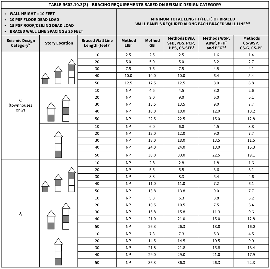 Open full-size table ↗
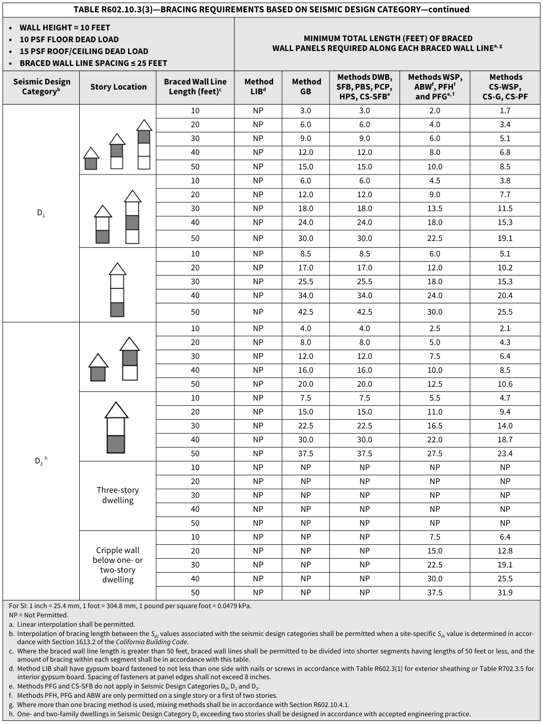 Open full-size table ↗
TABLE R602.10.3(4)—SEISMIC ADJUSTMENT FACTORS TO THE REQUIRED LENGTH OF WALL BRACING¶
TABLE R602.10.3(4)—SEISMIC ADJUSTMENT FACTORS TO THE REQUIRED LENGTH OF WALL BRACING
| ** ITEM** NUMBER |
** ADJUSTMENT** BASED ON |
** STORYg** | ** CONDITION** | ADJUSTMENT FACTORa, b [Multiply length from Table R602.10.3(3) by this factor] |
** APPLICABLE** METHODS |
|---|---|---|---|---|---|
| 1 | Wall height (Section R602.10.3.1) |
Any story | ≤ 10 feet | 1.0 | All methods |
| 1 | Wall height (Section R602.10.3.1) |
Any story | > 10 feet and ≤ 12 feet | 1.2 | All methods |
| 2 | Braced wall line spacing, townhouses in SDC C |
Any story | ≤ 35 feet | 1.0 | All methods |
| 2 | Braced wall line spacing, townhouses in SDC C |
Any story | > 35 feet and ≤ 50 feet | 1.43 | All methods |
| 3 | Braced wall line spacing, in SDC D0, D1, D2 c |
Any story | > 25 feet and ≤ 30 feet | 1.2 | All methods |
| 3 | Braced wall line spacing, in SDC D0, D1, D2 c |
Any story | > 30 feet and ≤ 35 feet | 1.4 | All methods |
| 4 | Wall dead load | Any story | > 8 psf and < 15 psf | 1.0 | All methods |
| 4 | Wall dead load | Any story | < 8psf | 0.85 | All methods |
| 5 | Roof/ for wall supporting |
1-, 2- or 3-story building | ≤ 15 psf | 1.0 | All methods |
| 5 | Roof/ for wall supporting |
2- or 3-story building | > 15 psf and ≤ 25 psf | 1.1 | All methods |
| 5 | Roof/ for wall supporting |
1-story building or top story |
> 15 psf and ≤ 25 psf | 1.2 | All methods |
| 6 | Walls with stone or masonry veneer, townhouses in SDC Cd, e |
Top story of a one-, two- or three-story building (original diagram) | See story diagram | 1.0 | All methods |
| 6 | Walls with stone or masonry veneer, townhouses in SDC Cd, e |
First story of a two-story building or second story of a three-story building (original diagram) | See story diagram | 1.5 | All methods |
| 6 | Walls with stone or masonry veneer, townhouses in SDC Cd, e |
First story of a three-story building (original diagram) | See story diagram | 1.5 | All methods |
| 7 | Walls with stone or masonry veneer, detached one- and two-family dwellings in SDC D0 – D2 d, f |
Any story | See Section R602.10.6.5.4 | See Section R602.10.6.5.4 | BV-WSP |
| 8 | Walls with stone or masonry veneer, detached one- and two-family dwellings in SDC D0 – D2 d, f |
First and second story of two-story dwelling |
Limited brick veneer on second story. See Section R602.10.6.5.3. |
1.2 | WSP, CS-WSP |
| 9 | Interior gypsum board finish (or equivalent) |
Any story | Omitted from inside face of braced wall panels |
1.5 | DWB, WSP, SFB, PBS, PCP, HPS, CS-WSP, CS-G, CS-SFB |
| 10 | Horizontal blocking | Any story | Horizontal blocking omitted |
2.0 | WSP, PBS, CS-WSP |
For SI: 1 foot = 304.8 mm, 1 pound per square foot = 0.0479 kPa. a. Linear interpolation shall be permitted. b. The total length of bracing required for a given wall line is the product of all applicable adjustment factors. c. The length-to-width ratio for the floor/roof diaphragm shall not exceed 3:1. d. Applies to stone or masonry veneer exceeding the first story height. e. The adjustment factor for stone or masonry veneer shall be applied to all exterior braced wall lines and all braced wall lines on the interior of the building, backing or perpen- dicular to and laterally supporting veneered walls. f. See Section R602.10.6.5 for requirements where stone or masonry veneer does not exceed the first-story height. g. One- and two-family dwellings in Seismic Design Category D2 exceeding two stories shall be designed in accordance with accepted engineering practice.
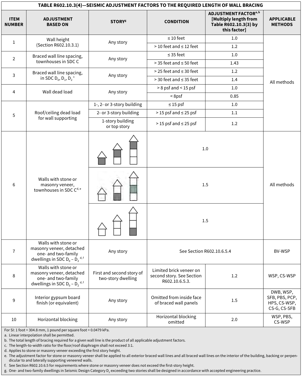 Open full-size table ↗
R602.10.3.1 Wall height for wood framing.¶
For determination of braced wall and panel adjustment factors in accordance with Section R602.10, wall height shall be the vertical distance from the lower edge of the bottom plate to the upper edge of the upper top plate determined in accordance with Figure R602.10.3.1.
FIGURE R602.10.3.1—WALL HEIGHT FOR WOOD FRAMING
WALL TOP PLATE
WALL TOP PLATE
WALL BOTTOM PLATE
TOP OF GROUND FLOOR SUPPORT
CONCRETE MASONRY FOUNDATION
CRAWL SPACE FRAMING
| WALL ST ROOF FRAMING • RAFTERS • CEILING JOIST • TRUSSES • OTHER |
||
| FLOOR SHEATHING | FLOOR SHEATHING | |
TOP STORY BELOW THE ROOF
WALL BOTTOM PLATE
GROUND/MIDDLE STORIES
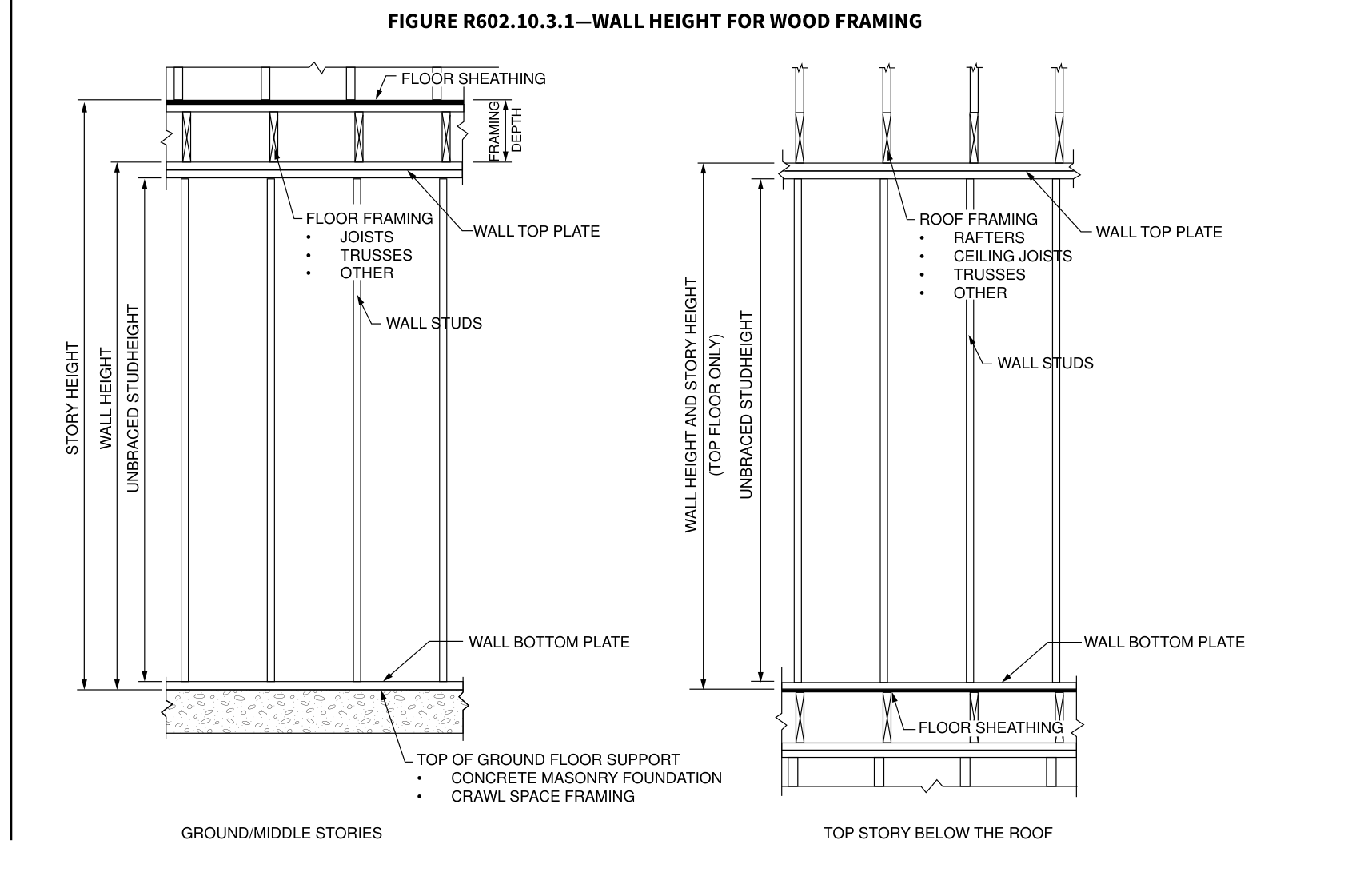 Open full-size illustration ↗
R602.10.4 Construction methods for braced wall panels.¶
Intermittent and continuously sheathed braced wall panels shall be constructed in accordance with this section and the methods listed in Table R602.10.4.
TABLE R602.10.4—BRACING METHODS
| Methods | Material | Minimum thickness | Figure | Connection criteriaa: fasteners | Connection criteriaa: spacing |
|---|---|---|---|---|---|
| Intermittent Bracing Methods |
LIB Let-in-bracing |
1 × 4 wood or approved metal straps at 45° to 60° angles for maximum 16″ stud spacing |
Original diagram | Wood: 2-8d common nails or 3-8d (2½″ long × 0.113″ dia.) nails |
Wood: per stud and top and bottom plates |
| Intermittent Bracing Methods |
LIB Let-in-bracing |
1 × 4 wood or approved metal straps at 45° to 60° angles for maximum 16″ stud spacing |
Original diagram | Metal strap: per manufacturer | Metal: per manufacturer |
| Intermittent Bracing Methods |
DWB Diagonal wood boards |
3/4″ (1″ nominal) for maximum 24″ stud spacing |
Original diagram | 2-8d (2½″ long × 0.113″ dia.) nails or 2-1¾″ long staples |
Per stud |
| Intermittent Bracing Methods |
WSP Wood structural panel (See Section R604) |
3/8″ | Original diagram | Exterior sheathing per Table R602.3(3) |
6″ edges 12″ field |
| Intermittent Bracing Methods |
WSP Wood structural panel (See Section R604) |
3/8″ | Original diagram | Interior sheathing per Table R602.3(1) or R602.3(2) |
Varies by fastener |
TABLE R602.10.4—BRACING METHODS—continued
| Methods | Material | Minimum thickness | Figure | Connection criteriaa: fasteners | Connection criteriaa: spacing |
|---|---|---|---|---|---|
| Intermittent Bracing Methods (continued) |
BV-WSPe Wood structural panels with stone or masonry veneer (See Section R602.10.6.5) |
7/16″ | See Figure R602.10.6.5.2 |
8d common (2½″ × 0.131) nails |
4″ at panel edges 12″ at intermediate supports 4″ at braced wall panel end posts |
| Intermittent Bracing Methods (continued) |
SFB Structural fiberboard sheathing |
1/2″ or 25/32″ for maximum 16″ stud spacing |
Original diagram | 1½″ long × 0.12″ dia. (for 1/2″ thick sheathing) 1¾″ long × 0.12″ dia. (for 25/32″ thick sheath- ing) galvanized roofing nails |
3″ edges 6″ field |
| Intermittent Bracing Methods (continued) |
GB Gypsum board |
1/2″ | Original diagram | Nails or screws per Table R602.3(1) for exterior locations |
For all braced wall panel locations: 7″ edges (including top and bottom plates) 7″ field |
| Intermittent Bracing Methods (continued) |
GB Gypsum board |
1/2″ | Original diagram | Nails or screws per Table R702.3.5 for interior locations |
For all braced wall panel locations: 7″ edges (including top and bottom plates) 7″ field |
| Intermittent Bracing Methods (continued) |
PBS Particleboard sheathing (See Section R605) |
3/8″ or 1/2″ for maximum 16″ stud spacing |
Original diagram | For 3/8″, 6d common (2″ long × 0.113″ dia.) nails; For 1/2″, 8d common (2½″ long × 0.131″ dia.) nails |
3″ edges 6″ field |
| Intermittent Bracing Methods (continued) |
PCP Portland cement plaster |
See Section R703.6 for maximum 16″ stud spacing |
Original diagram | 1½″ long, 11 gage, 0.120" dia., 7/16″ dia. head nails or 7/8″ long, 16 gage staples |
6″ o.c. on all framing members |
| Intermittent Bracing Methods (continued) |
HPS Hardboard panel siding |
7/16″ for maximum 16″ stud spacing |
Original diagram | 0.092″ dia., 0.225″ dia. head nails with length to accommo- date 1½″ penetration into studs |
4″ edges 8″ field |
| Intermittent Bracing Methods (continued) |
ABW Alternate braced wall |
3/8″ | Original diagram | See Section R602.10.6.1 | See Section R602.10.6.1 |
| Intermittent Bracing Methods (continued) |
PFH Portal frame with hold-downs |
3/8″ | Original diagram | See Section R602.10.6.2 | See Section R602.10.6.2 |
| Intermittent Bracing Methods (continued) |
PFG Portal frame at garage |
7/16″ | Original diagram | See Section R602.10.6.3 | See Section R602.10.6.3 |
| Continuous Sheathing Methods |
CS-WSP Continuously sheathed wood structural panel |
3/8″ | Original diagram | Exterior sheathing per Table R602.3(3) |
6″ edges 12″ field |
| Continuous Sheathing Methods |
CS-WSP Continuously sheathed wood structural panel |
3/8″ | Original diagram | Interior sheathing per Table R602.3(1) or R602.3(2) |
Varies by fastener |
| Continuous Sheathing Methods |
CS-Gb, c Continuously sheathed wood structural panel adjacent to garage openings |
3/8″ | Original diagram | See Method CS-WSP | See Method CS-WSP |
| Continuous Sheathing Methods |
CS-PF Continuously sheathed portal frame |
7/16″ | Original diagram | See Section R602.10.6.4 | See Section R602.10.6.4 |
TABLE R602.10.4—BRACING METHODS—continued
| Methods | Material | Minimum thickness | Figure | Connection criteriaa: fasteners | Connection criteriaa: spacing |
|---|---|---|---|---|---|
| Continuous Sheathing Methods (continued) |
CS-SFBd Continuously sheathed structural fiberboard |
1/2″ or 25/32″ for maximum 16″ stud spacing |
Original diagram | 1½″ long × 0.12″ dia. (for 1/2″ thick sheathing) 1¾″ long × 0.12″ dia. (for 25/32″ thick sheathing) galvanized roofing nails |
3″ edges 6″ field |
For SI: 1 inch = 25.4 mm, 1 foot = 304.8 mm, 1 degree = 0.0175 rad, 1 pound per square foot = 47.8 N/m2, 1 mile per hour = 0.447 m/s.
a. Adhesive attachment of wall sheathing, including Method GB, shall not be permitted in Seismic Design Categories C, D0, D1 and D2.
b. Applies to panels next to garage door opening where supporting gable end wall or roof load only. Shall only be used on one wall of the garage. In Seismic Design Categories D0, D1 and D2, roof covering dead load shall not exceed 3 psf.
c. Garage openings adjacent to a Method CS-G panel shall be provided with a header in accordance with Table R602.7(1). A full-height clear opening shall not be permitted adja- cent to a Method CS-G panel.
d. Method CS-SFB does not apply in Seismic Design Categories D0, D1 and D2.
e. Method applies to detached one- and two-family dwellings in Seismic Design Categories D0 through D2 only.
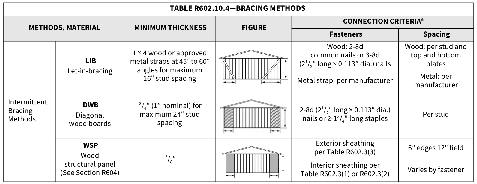 Open full-size table ↗
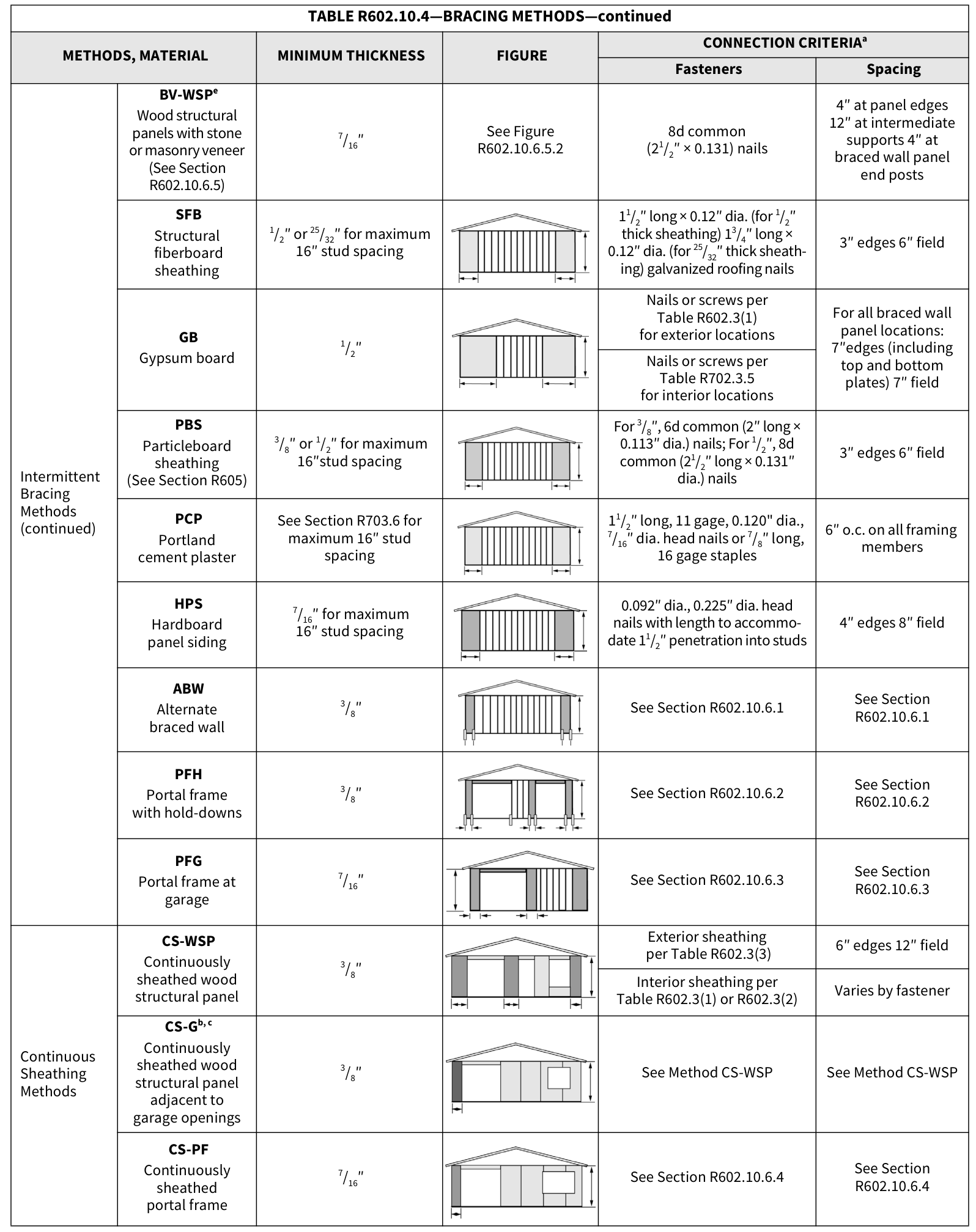 Open full-size table ↗
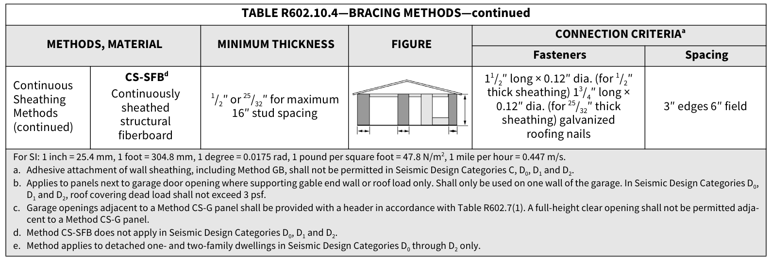 Open full-size table ↗
R602.10.4.1 Mixing methods.¶
Mixing of bracing methods shall be permitted as follows:
- Mixing intermittent bracing and continuous sheathing methods from story to story shall be permitted.
- Mixing intermittent bracing methods from braced wall line to braced wall line within a story shall be permitted. In regions within Seismic Design Categories A, B and C where the ultimate design wind speed is less than or equal to 130 mph (58 m/s), mixing of intermittent bracing and continuous sheathing methods from braced wall line to braced wall line within a story shall be permitted.
- Mixing intermittent bracing methods along a braced wall line shall be permitted in Seismic Design Categories A and B, and detached dwellings in Seismic Design Category C, provided that the length of required bracing in accordance with Table R602.10.3(1) or R602.10.3(3) is the highest value of all intermittent bracing methods used.
- Mixing of continuous sheathing methods CS-WSP, CS-G and CS-PF along a braced wall line shall be permitted. Intermittent methods ABW, PFH and PFG shall be permitted to be used along a braced wall line with continuous sheathed methods, provided that the length of required bracing for that braced wall line is determined in accordance with Table R602.10.3(1) or R602.10.3(3) using the highest value of the bracing methods used.
- In Seismic Design Categories A and B, and for detached one- and two-family dwellings in Seismic Design Category C, mixing of intermittent bracing methods along the interior portion of a braced wall line with continuous sheathing methods CS-WSP, CS-G and CS-PF along the exterior portion of the same braced wall line shall be permitted. The length of required bracing shall be the highest value of all intermittent bracing methods used in accordance with Table R602.10.3(1) or R602.10.3(3) as adjusted by Tables R602.10.3(2) and R602.10.3(4), respectively. The requirements of Section R602.10.7 shall apply to each end of the continuously sheathed portion of the braced wall line.
R602.10.4.2 Continuous sheathing methods.¶
Continuous sheathing methods require structural panel sheathing to be used on all sheathable surfaces on one side of a braced wall line including areas above and below openings and gable end walls and shall meet the requirements of Section R602.10.7. R602.10.4.3 Braced wall panel interior finish material. Braced wall panels shall have gypsum wall board installed on the side of the wall opposite the bracing material. Gypsum wall board shall be not less than 1/2 inch (12.7 mm) in thickness and be fastened with nails or screws in accordance with Table R602.3(1) for exterior sheathing or Table R702.3.5 for interior gypsum wall board. Spacing of fasteners at panel edges for gypsum wall board opposite Method LIB bracing shall not exceed 8 inches (203 mm). Interior finish material shall not be glued in Seismic Design Categories D 0, D 1 and D 2 . Exceptions:
- Interior finish material is not required opposite wall panels that are braced in accordance with Methods GB, BVWSP, ABW, PFH, PFG and CS-PF, unless otherwise required by Section R302.6.
- An approved interior finish material with an in-plane shear resistance equivalent to gypsum board shall be permitted to be substituted, unless otherwise required by Section R302.6.
- Except for Method LIB, gypsum wall board is permitted to be omitted provided that the required length of bracing in Tables R602.10.3(1) and R602.10.3(3) is multiplied by the appropriate adjustment factor in Tables R602.10.3(2) and R602.10.3(4), respectively, unless otherwise required by Section R302.6.
R602.10.4.4 Panel joints.¶
Vertical joints of panel sheathing shall occur over and be fastened to common studs. Horizontal joints of panel sheathing in braced wall panels shall occur over and be fastened to common blocking of a thickness of 1 1/2 inches (38 mm) or greater.
Exceptions:
For methods WSP and CS-WSP, blocking of horizontal joints is permitted to be omitted when adjustment factor No. 8 of Table R602.10.3(2) or No. 10 of Table R602.10.3(4) is applied.
Vertical joints of panel sheathing shall be permitted to occur over double studs, where adjoining panel edges are attached to separate studs with the required panel edge fastening schedule, and the adjacent studs are attached together with two rows of 10d box nails [3 inches by 0.128 inch (76.2 mm by 3.25 mm)] at 10 inches o.c. (254 mm).
Blocking at horizontal joints shall not be required in wall segments that are not counted as braced wall panels.
Where Method GB panels are installed horizontally, blocking of horizontal joints is not required.
R602.10.5 Minimum length of a braced wall panel.¶
The minimum length of a braced wall panel shall comply with Table R602.10.5. For Methods CS-WSP and CS-SFB, the minimum panel length shall be based on the adjacent clear opening height in accordance with Table R602.10.5 and Figure R602.10.5. Where a panel has an opening on either side of differing heights, the taller opening height shall be used to determine the panel length.
TABLE R602.10.5—MINIMUM LENGTH OF BRACED WALL PANELS
| ** METHOD (See Table R602.10.4)** | ** METHOD (See Table R602.10.4)** | ** MINIMUM LENGTHa (inches)** | ** MINIMUM LENGTHa (inches)** | ** MINIMUM LENGTHa (inches)** | ** MINIMUM LENGTHa (inches)** | ** MINIMUM LENGTHa (inches)** | CONTRIBUTING LENGTH (inches) |
|---|---|---|---|---|---|---|---|
| ** METHOD (See Table R602.10.4)** | ** METHOD (See Table R602.10.4)** | ** Wall Height** | ** Wall Height** | ** Wall Height** | ** Wall Height** | ** Wall Height** | CONTRIBUTING LENGTH (inches) |
| ** METHOD (See Table R602.10.4)** | ** METHOD (See Table R602.10.4)** | ** 8 feet** | ** 9 feet** | ** 10 feet** | ** 11 feet** | ** 12 feet** | CONTRIBUTING LENGTH (inches) |
| DWB, WSP, SFB, PBS, PCP, HPS, BV-WSP | DWB, WSP, SFB, PBS, PCP, HPS, BV-WSP | 48 | 48 | 48 | 53 | 58 | Actualb |
| GB | GB | 48 | 48 | 48 | 53 | 58 | Double sided = Actual Single sided = 0.5 × Actual |
| LIB | LIB | 55 | 62 | 69 | NP | NP | Actualb |
| ABW | SDC A, B and C, ultimate design wind speed < 140 mph |
28 | 32 | 34 | 38 | 42 | 48 |
| ABW | SDC D0, D1 and D2, ultimate design wind speed < 140 mph |
32 | 32 | 34 | NP | NP | 48 |
| CS-G | CS-G | 24 | 27 | 30 | 33 | 36 | Actualb |
| CS-WSP, CS-SFB |
Adjacent clear opening height (inches) |
Actualb | |||||
| CS-WSP, CS-SFB |
≤ 64 | 24 | 27 | 30 | 33 | 36 | Actualb |
| CS-WSP, CS-SFB |
68 | 26 | 27 | 30 | 33 | 36 | Actualb |
| CS-WSP, CS-SFB |
72 | 27 | 27 | 30 | 33 | 36 | Actualb |
| CS-WSP, CS-SFB |
76 | 30 | 29 | 30 | 33 | 36 | Actualb |
| CS-WSP, CS-SFB |
80 | 32 | 30 | 30 | 33 | 36 | Actualb |
| CS-WSP, CS-SFB |
84 | 35 | 32 | 32 | 33 | 36 | Actualb |
| CS-WSP, CS-SFB |
88 | 38 | 35 | 33 | 33 | 36 | Actualb |
| CS-WSP, CS-SFB |
92 | 43 | 37 | 35 | 35 | 36 | Actualb |
| CS-WSP, CS-SFB |
96 | 48 | 41 | 38 | 36 | 36 | Actualb |
| CS-WSP, CS-SFB |
100 | — | 44 | 40 | 38 | 38 | Actualb |
| CS-WSP, CS-SFB |
104 | — | 49 | 43 | 40 | 39 | Actualb |
| CS-WSP, CS-SFB |
Adjacent clear opening height (inches) |
Actualb | |||||
| CS-WSP, CS-SFB |
108 | — | 54 | 46 | 43 | 41 | Actualb |
| CS-WSP, CS-SFB |
112 | — | — | 50 | 45 | 43 | Actualb |
| CS-WSP, CS-SFB |
116 | — | — | 55 | 48 | 45 | Actualb |
| CS-WSP, CS-SFB |
120 | — | — | 60 | 52 | 48 | Actualb |
| CS-WSP, CS-SFB |
124 | — | — | — | 56 | 51 | Actualb |
| CS-WSP, CS-SFB |
128 | — | — | — | 61 | 54 | Actualb |
| CS-WSP, CS-SFB |
132 | — | — | — | 66 | 58 | Actualb |
| CS-WSP, CS-SFB |
136 | — | — | — | — | 62 | Actualb |
| CS-WSP, CS-SFB |
140 | — | — | — | — | 66 | Actualb |
| CS-WSP, CS-SFB |
144 | — | — | — | — | 72 | Actualb |
TABLE R602.10.5—MINIMUM LENGTH OF BRACED WALL PANELS—continued
| METHOD (See Table R602.10.4) | METHOD (See Table R602.10.4) | Portal header height | Portal header height | Portal header height | Portal header height | Portal header height | CONTRIBUTING LENGTH (inches) |
|---|---|---|---|---|---|---|---|
| METHOD (See Table R602.10.4) | METHOD (See Table R602.10.4) | 8 feet | 9 feet | 10 feet | 11 feet | 12 feet | CONTRIBUTING LENGTH (inches) |
| PFH | Supporting roof only | 16 | 16 | 16 | Note c | Note c | 48 |
| PFH | Supporting one story and roof | 24 | 24 | 24 | Note c | Note c | 48 |
| PFG | PFG | 24 | 27 | 30 | Note d | Note d | 1.5 × Actualb |
| CS-PF | SDC A, B and C | 16 | 18 | 20 | Note e | Note e | 1.5 × Actualb |
| CS-PF | SDC D0, D1 and D2 | 16 | 18 | 20 | Note e | Note e | Actualb |
For SI: 1 inch = 25.4 mm, 1 foot = 304.8 mm, 1 mile per hour = 0.447 m/s. NP = Not Permitted. a. Linear interpolation shall be permitted. b. Use the actual length where it is greater than or equal to the minimum length. The actual length of Methods CS-G, CS-WSP, CS-SFB, PFH, PFG and CS-PF is the length of the full-height sheathed section. c. Maximum header height for PFH is 10 feet in accordance with Figure R602.10.6.2, but wall height shall be permitted to be increased to 12 feet with pony wall. d. Maximum header height for PFG is 10 feet in accordance with Figure R602.10.6.3, but wall height shall be permitted to be increased to 12 feet with pony wall. e. Maximum header height for CS-PF is 10 feet in accordance with Figure R602.10.6.4, but wall height shall be permitted to be increased to 12 feet with pony wall.
FIGURE R602.10.5—BRACED WALL PANELS WITH CONTINUOUS SHEATHING
| CLEAR OPENING HEIGHT CLEAR OPENING HEIGHT |
CLEAR OPENING HEIGHT CLEAR OPENING HEIGHT |
CLEAR OPENING HEIGHT |
|||
|---|---|---|---|---|---|
| CLEAR OPENING HEIGHT |
CLEAR OPENING HEIGHT |
CLEAR OPENING HEIGHT |
CLEAR OPENING HEIGHT |
CLEAR OPENING HEIGHT |
|
| PANEL PANEL PANEL |
PANEL PANEL PANEL |
PANEL PANEL PANEL |
PANEL PANEL PANEL |
PANEL PANEL PANEL |
PANEL PANEL PANEL |
LENGTH LENGTH LENGTH
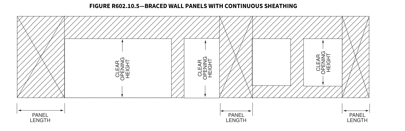 Open full-size illustration ↗
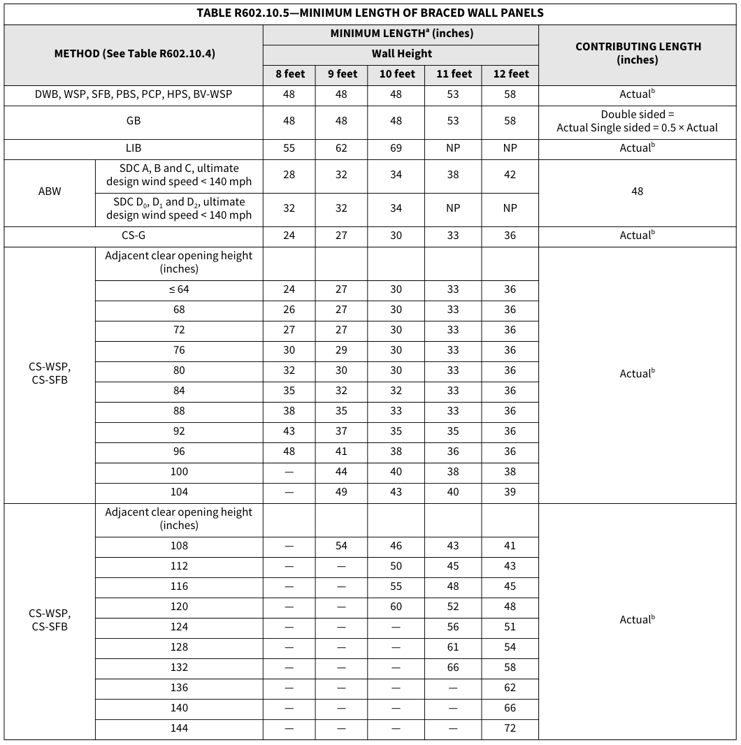 Open full-size table ↗
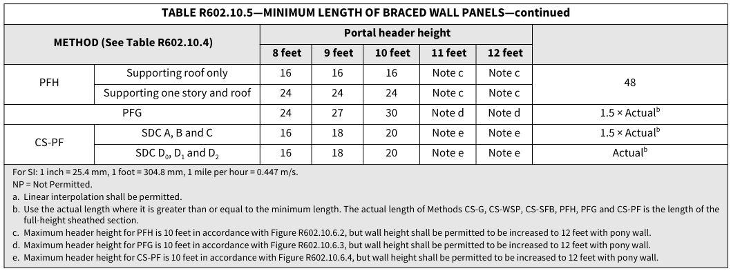 Open full-size table ↗
R602.10.5.1 Contributing length.¶
For purposes of computing the required length of bracing in Tables R602.10.3(1) and R602.10.3(3), the contributing length of each braced wall panel shall be as specified in Table R602.10.5.
R602.10.5.2 Partial credit. For Methods DWB, WSP, SFB, PBS, PCP and HPS in Seismic Design Categories A, B and C, panels between 36 inches and 48 inches (914 mm and 1219 mm) in length shall be considered a braced wall panel and shall be permitted to partially contribute toward the required length of bracing in Tables R602.10.3(1) and R602.10.3(3), and the contributing length shall be determined from Table R602.10.5.2.
TABLE R602.10.5.2—PARTIAL CREDIT FOR BRACED WALL PANELS LESS THAN 48 INCHES IN ACTUAL…¶
TABLE R602.10.5.2—PARTIAL CREDIT FOR BRACED WALL PANELS LESS THAN 48 INCHES IN ACTUAL LENGTH
| ** ACTUAL LENGTH OF BRACED WALL PANEL** (inches) |
** CONTRIBUTING LENGTH OF BRACED WALL PANEL** (inches)a |
** CONTRIBUTING LENGTH OF BRACED WALL PANEL** (inches)a |
|---|---|---|
| ** ACTUAL LENGTH OF BRACED WALL PANEL** (inches) |
** 8-foot Wall Height** | ** 9-foot Wall Height** |
| 48 | 48 | 48 |
| 42 | 36 | 36 |
| 36 | 27 | NA |
For SI: 1 inch = 25.4 mm, 1 foot = 304.8 mm. NA = Not Applicable. a. Linear interpolation shall be permitted.
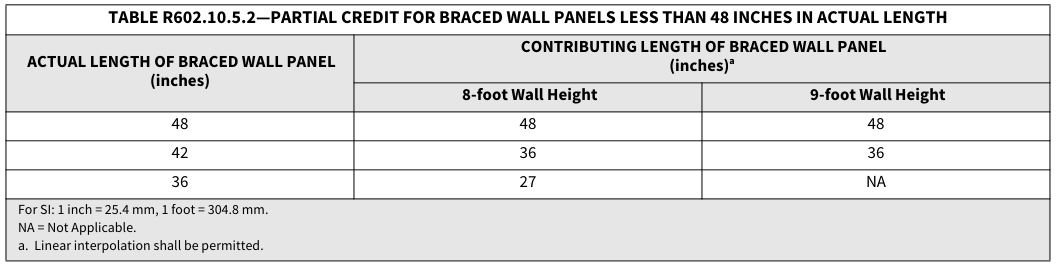 Open full-size table ↗
R602.10.6 Construction of Methods ABW, PFH, PFG, CS-PF and BV-WSP.¶
Methods ABW, PFH, PFG, CS-PF and BV-WSP shall be constructed as specified in Sections R602.10.6.1 through R602.10.6.5. For the purposes of determining braced wall panel spacing and end distance, the edge of Methods PFH, PFG and CS-PF shall be defined as the end of the header.
R602.10.6.1 Method ABW: Alternate braced wall panels. Method ABW braced wall panels shall be constructed in accordance with Figure R602.10.6.1. The hold-down force shall be in accordance with Table R602.10.6.1.
TABLE R602.10.6.1—MINIMUM HOLD-DOWN FORCES FOR METHOD ABW BRACED WALL PANELS¶
TABLE R602.10.6.1—MINIMUM HOLD-DOWN FORCES FOR METHOD ABW BRACED WALL PANELS
| ** SEISMIC DESIGN CATEGORY AND WIND SPEED** | SUPPORTING/ |
** HOLD-DOWN FORCE (pounds)** | ** HOLD-DOWN FORCE (pounds)** | ** HOLD-DOWN FORCE (pounds)** | ** HOLD-DOWN FORCE (pounds)** | ** HOLD-DOWN FORCE (pounds)** |
|---|---|---|---|---|---|---|
| ** SEISMIC DESIGN CATEGORY AND WIND SPEED** | SUPPORTING/ |
** Height of Braced Wall Panel** | ** Height of Braced Wall Panel** | ** Height of Braced Wall Panel** | ** Height of Braced Wall Panel** | ** Height of Braced Wall Panel** |
| ** SEISMIC DESIGN CATEGORY AND WIND SPEED** | SUPPORTING/ |
** 8 feet** | ** 9 feet** | ** 10 feet** | ** 11 feet** | ** 12 feet** |
| SDC A, B and C Ultimate design wind speed < 140 mph |
One story | 1,800 | 1,800 | 1,800 | 2,000 | 2,200 |
| SDC A, B and C Ultimate design wind speed < 140 mph |
First of two stories | 3,000 | 3,000 | 3,000 | 3,300 | 3,600 |
| SDC D0, D1 and D2 Ultimate design wind speed <140 mph |
One story | 1,800 | 1,800 | 1,800 | NP | NP |
| SDC D0, D1 and D2 Ultimate design wind speed <140 mph |
First of two stories | 3,000 | 3,000 | 3,000 | NP | NP |
For SI: 1 foot = 304.8 mm, 1 pound = 4.45 N, 1 mile per hour = 0.447 m/s. NP = Not Permitted.
FIGURE R602.10.6.1—METHOD ABW—ALTERNATE BRACED WALL PANEL
For SI: 1 inch = 25.4 mm.
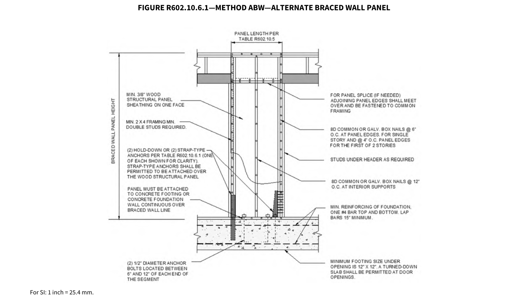 Open full-size illustration ↗
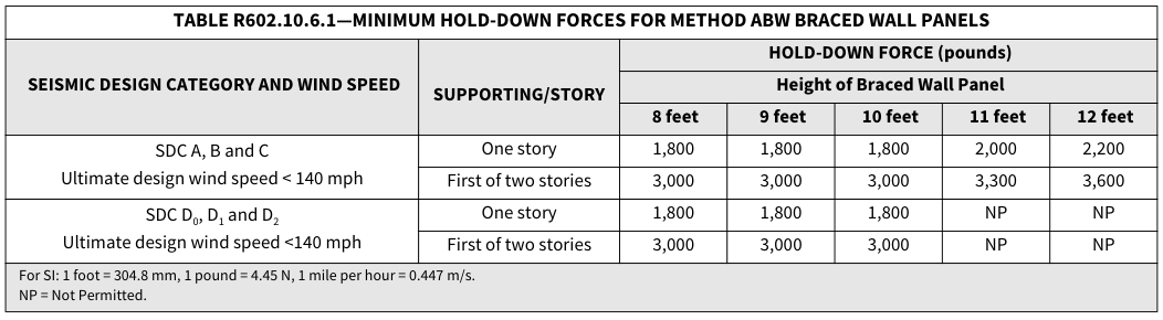 Open full-size table ↗
R602.10.6.2 Method PFH: Portal frame with hold-downs.¶
Method PFH braced wall panels shall be constructed in accordance with Figure R602.10.6.2.
FIGURE R602.10.6.2—METHOD PFH—PORTAL FRAME WITH HOLD-DOWNS
For SI: 1 inch = 25.4 mm, 1 foot = 304.8 mm. Note: Header shall not extend over more than one opening.
R602.10.6.3 Method PFG: Portal frame at garage d oor op enings in Se ismic Design Categories A, B and C. Where supporting a roof or one story and a roof, a Method PFG braced wall panel constructed in accordance with Figure R602.10.6.3 shall be
permitted on either side of garage door openings.
FIGURE R602.10.6.3—METHOD PFG—PORTAL FRAME AT GARAGE DOOR OPENINGS IN SEISMIC DESIGN CATEGORIES A, B AND C
EXTENT OF HEADER WITH DOUBLE PORTAL FRAMES (TWO BRACED WALL PANELS)
EXTENT OF HEADER WITH SINGLE PORTAL FRAME
TENSION STRAP PER TABLE 602.10.6.4 (ON OPPOSITE SIDE OF SHEATHING)
IF NEEDED, PANEL SPLICE EDGES SHALL OCCUR OVER AND BE NAILED TO COMMON BLOCKING WITHIN THE MIDDLE 24" OF THE PORTAL-LEG HEIGHT. ONE ROW OF 3" O.C. NAILING IS REQUIRED IN EACH PANEL EDGE.
TYPICAL PORTAL FRAME CONSTRUCTION
MIN. DOUBLE 2 x 4 POST (KING AND JACK STUD) NUMBER OF JACK STUDS PER TABLES R602.7(1) & (2)
INTERMITTENT BRACED WALL PANEL REQUIRED ADJACENT OPENING FOR SINGLE PORTAL FRAME
ANCHOR BOLTS PER SECTION R403.1.6
| MIN. 3" x 11¼" NET HEADER STEEL HEADER PROHIBITED IF ½" SPACER IS USED, PLACE ON BACK-SIDE OF HEADER |
|||||
| FASTEN SHEATHING TO HEADER WITH 8D COMMON OR GALVANIZED BOX NAILS IN 3" GRID PATTERN AS SHOWN HEADER TO JACK-STUD STRAP PER TABLE R602.10.6.4 ON BOTH SIDES OF OPENING OPPOSITE SIDE OF SHEATHING MIN. DOUBLE 2" x 4" FRAMING COVERED WITH MIN. 7/16" THICK WOOD STRUCTURAL PANEL SHEATHING WITH 8D COMMON OR GALVANIZED BOX NAILS AT 3" O.C. IN ALL FRAMING (STUDS AND SILLS) AS SHOWN TYP. MIN. LENGTH OF PANEL PER TABLE R602.10.5 MIN. (2) ½" DIAMETER ANCHOR BOLTS INSTALLED PER SECTION R403.1.6 WITH 2" x 2" x3/16" PLATE WASHER |
|||||
FRONT ELEVATION SECTION
For SI: 1 inch = 25.4 mm, 1 foot = 304.8 mm. Note: Header shall not extend over more than one opening.
| RAP PER 0.6.4 TE SIDE NG) NEL S SHALL AND BE MMON THIN THE F THE HEIGHT. 3" O.C. QUIRED L EDGE. L RUCTION x 4 POST K STUD) CK BLES BRACED QUIRED NING RTAL TS PER 3.1.6 |
FASTEN KING ST TO HEADER WIT 16D SINKERS FASTEN TOP PLATE TO HEADER WIT TWO ROWS OF 16 SINKER NAIL 3" O.C. TYP. MIN. 7/16" WO STRUCTURA PANEL SHEATHING |
||||
|---|---|---|---|---|---|
| RAP PER 0.6.4 TE SIDE NG) L RUCTION BRACED QUIRED NING RTAL x 4 POST K STUD) CK BLES TS PER 3.1.6 NEL S SHALL AND BE MMON THIN THE F THE HEIGHT. 3" O.C. QUIRED L EDGE. |
|||||
| RAP PER 0.6.4 TE SIDE NG) L RUCTION BRACED QUIRED NING RTAL x 4 POST K STUD) CK BLES TS PER 3.1.6 NEL S SHALL AND BE MMON THIN THE F THE HEIGHT. 3" O.C. QUIRED L EDGE. |
|||||
| RAP PER 0.6.4 TE SIDE NG) L RUCTION BRACED QUIRED NING RTAL x 4 POST K STUD) CK BLES TS PER 3.1.6 NEL S SHALL AND BE MMON THIN THE F THE HEIGHT. 3" O.C. QUIRED L EDGE. |
|||||
| RAP PER 0.6.4 TE SIDE NG) L RUCTION BRACED QUIRED NING RTAL x 4 POST K STUD) CK BLES TS PER 3.1.6 NEL S SHALL AND BE MMON THIN THE F THE HEIGHT. 3" O.C. QUIRED L EDGE. |
|||||
| RAP PER 0.6.4 TE SIDE NG) L RUCTION BRACED QUIRED NING RTAL x 4 POST K STUD) CK BLES TS PER 3.1.6 NEL S SHALL AND BE MMON THIN THE F THE HEIGHT. 3" O.C. QUIRED L EDGE. |
D D |
D D |
|||
| RAP PER 0.6.4 TE SIDE NG) L RUCTION BRACED QUIRED NING RTAL x 4 POST K STUD) CK BLES TS PER 3.1.6 NEL S SHALL AND BE MMON THIN THE F THE HEIGHT. 3" O.C. QUIRED L EDGE. |
D D |
D D |
|||
| RAP PER 0.6.4 TE SIDE NG) L RUCTION BRACED QUIRED NING RTAL x 4 POST K STUD) CK BLES TS PER 3.1.6 NEL S SHALL AND BE MMON THIN THE F THE HEIGHT. 3" O.C. QUIRED L EDGE. |
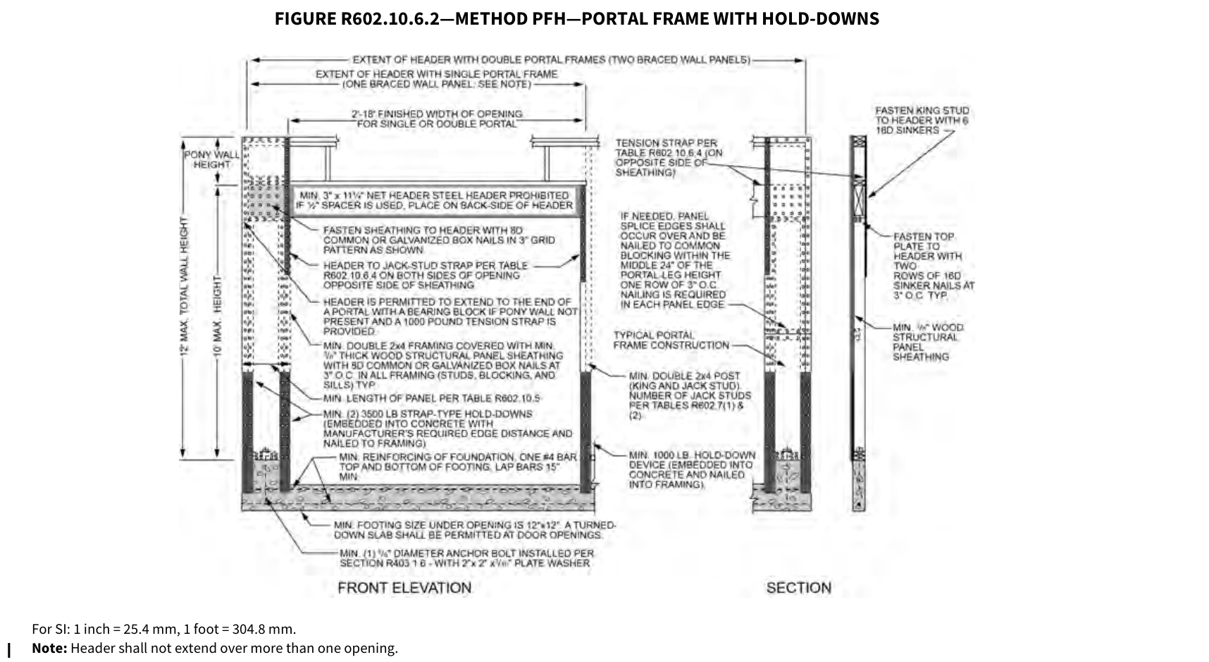 Open full-size illustration ↗
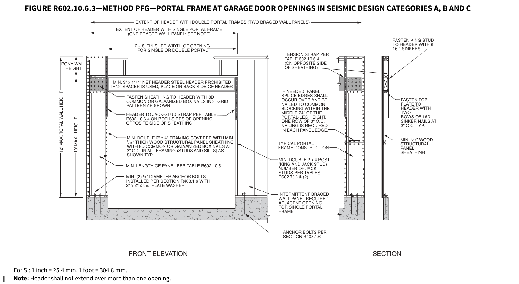 Open full-size illustration ↗
R602.10.6.4 Method CS-PF: Continuously sheathed portal frame.¶
Continuously sheathed portal frame braced wall panels shall be constructed in accordance with Figure R602.10.6.4 and Table R602.10.6.4.
TABLE R602.10.6.4—TENSION STRAP CAPACITY FOR RESISTING WIND
PRESSURES PERPENDICULAR TO METHODS PFH, PFG AND CS-PF BRACED WALL PANELSa
| ** MINIMUM WALL STUD** FRAMING NOMINAL SIZE AND GRADE |
** MAXIMUM** PONY WALL HEIGHT (feet) |
** MAXIMUM** TOTAL WALL HEIGHT (feet) |
** MAXIMUM** OPENING WIDTH (feet) |
** TENSION STRAP CAPACITY REQUIRED** (pounds)a |
** TENSION STRAP CAPACITY REQUIRED** (pounds)a |
** TENSION STRAP CAPACITY REQUIRED** (pounds)a |
** TENSION STRAP CAPACITY REQUIRED** (pounds)a |
** TENSION STRAP CAPACITY REQUIRED** (pounds)a |
** TENSION STRAP CAPACITY REQUIRED** (pounds)a |
|---|---|---|---|---|---|---|---|---|---|
| ** MINIMUM WALL STUD** FRAMING NOMINAL SIZE AND GRADE |
** MAXIMUM** PONY WALL HEIGHT (feet) |
** MAXIMUM** TOTAL WALL HEIGHT (feet) |
** MAXIMUM** OPENING WIDTH (feet) |
** Ultimate Design Wind Speed****Vult (mph)** |
** Ultimate Design Wind Speed****Vult (mph)** |
** Ultimate Design Wind Speed****Vult (mph)** |
** Ultimate Design Wind Speed****Vult (mph)** |
** Ultimate Design Wind Speed****Vult (mph)** |
** Ultimate Design Wind Speed****Vult (mph)** |
| ** MINIMUM WALL STUD** FRAMING NOMINAL SIZE AND GRADE |
** MAXIMUM** PONY WALL HEIGHT (feet) |
** MAXIMUM** TOTAL WALL HEIGHT (feet) |
** MAXIMUM** OPENING WIDTH (feet) |
** ≤ 110** | ** 115** | ** 130** | ** ≤ 110** | ** 115** | ** 130** |
| ** MINIMUM WALL STUD** FRAMING NOMINAL SIZE AND GRADE |
** MAXIMUM** PONY WALL HEIGHT (feet) |
** MAXIMUM** TOTAL WALL HEIGHT (feet) |
** MAXIMUM** OPENING WIDTH (feet) |
** Exposure B** | ** Exposure B** | ** Exposure B** | ** Exposure C** | ** Exposure C** | ** Exposure C** |
| 2 × 4 No. 2 Grade | 0 | 10 | 18 | 1,000 | 1,000 | 1,000 | 1,000 | 1,000 | 1,050 |
| 2 × 4 No. 2 Grade | 1 | 10 | 9 | 1,000 | 1,000 | 1,000 | 1,000 | 1,000 | 1,750 |
| 2 × 4 No. 2 Grade | 1 | 10 | 16 | 1,000 | 1,025 | 2,050 | 2,075 | 2,500 | 3,950 |
| 2 × 4 No. 2 Grade | 1 | 10 | 18 | 1,000 | 1,275 | 2,375 | 2,400 | 2,850 | DR |
| 2 × 4 No. 2 Grade | 2 | 10 | 9 | 1,000 | 1,000 | 1,475 | 1,500 | 1,875 | 3,125 |
| 2 × 4 No. 2 Grade | 2 | 10 | 16 | 1,775 | 2,175 | 3,525 | 3,550 | 4,125 | DR |
| 2 × 4 No. 2 Grade | 2 | 10 | 18 | 2,075 | 2,500 | 3,950 | 3,975 | DR | DR |
| 2 × 4 No. 2 Grade | 2 | 12 | 9 | 1,150 | 1,500 | 2,650 | 2,675 | 3,175 | DR |
| 2 × 4 No. 2 Grade | 2 | 12 | 16 | 2,875 | 3,375 | DR | DR | DR | DR |
| 2 × 4 No. 2 Grade | 2 | 12 | 18 | 3,425 | 3,975 | DR | DR | DR | DR |
| 2 × 4 No. 2 Grade | 4 | 12 | 9 | 2,275 | 2,750 | DR | DR | DR | DR |
| 2 × 4 No. 2 Grade | 4 | 12 | 12 | 3,225 | 3,775 | DR | DR | DR | DR |
| 2 × 6 Stud Grade | 2 | 12 | 9 | 1,000 | 1,000 | 1,700 | 1,700 | 2,025 | 3,050 |
| 2 × 6 Stud Grade | 2 | 12 | 16 | 1,825 | 2,150 | 3,225 | 3,225 | 3,675 | DR |
| 2 × 6 Stud Grade | 2 | 12 | 18 | 2,200 | 2,550 | 3,725 | 3,750 | DR | DR |
| 2 × 6 Stud Grade | 4 | 12 | 9 | 1,450 | 1,750 | 2,700 | 2,725 | 3,125 | DR |
| 2 × 6 Stud Grade | 4 | 12 | 16 | 2,050 | 2,400 | DR | DR | DR | DR |
| 2 × 6 Stud Grade | 4 | 12 | 18 | 3,350 | 3,800 | DR | DR | DR | DR |
For SI: 1 foot = 304.8 mm, 1 pound = 4.45 N, 1 mile per hour = 0.447 m/s. DR = Design Required. a. Straps shall be installed in accordance with manufacturer’s recommendations.
FIGURE R602.10.6.4—METHOD CS-PF—CONTINUOUSLY SHEATHED PORTAL FRAME PANEL CONSTRUCTION
PLATE TO JOIST
APPROVED BAND OR RIM JOIST
NAIL SOLE PLATE TO JOIST PER TABLE R602.3(1)
APPROVED BAND OR RIM JOIST
| MIN. 3″x11¼″ NET HEADER STEEL HEADER PROHIBITED IF ½″ SPACER IS USED, PLACE ON BACK-SIDE OF HEADER |
|||||||
OVER RAISED WOOD FLOOR - FRAMING ANCHOR OPTION (WHERE PORTAL SHEATHING DOES NOT LAP OVER BAND OR RIM JOIST)
ATTACH SHEATHING TO BAND OR RIM JOIST WITH8D COMMON NAILS AT 3 ″ O.C. TOP AND BOTTOM
| OVERLAP W S OH RO E O RA ID T M HS JIT N OR G ISU T TC OT U TORA PL O P FA BN AE NL D N T TAOA B I JL LO ES I O S RTL 6 E 0P 2EP .3RL (A 1T )E 9¼″ WOOD STRUCTURAL PANEL SHEATHING OVER AP |
W S OH RO E O RA ID T M HS JIT N OR G ISU T TC OT U TORA PL O P FA BN AE NL D N T TAOA B I JL LO ES I O S RTL 6 E 0P 2EP .3RL (A 1T )E | |||
|---|---|---|---|---|
| WOOD STRUCTURAL PANEL SHEATHING OVER AP WOOD STRUCTURAL PANEL SHEATHING TO TOP OF BAND OR RIM JOIST OVERLAP 9¼″ NAIL SOLE PLATE TO JOIST PER TABLE R602.3(1) |
OVER RAISED WOOD FLOOR - OVERLAP OPTION (WHERE PORTAL SHEATHING LAPS OVER BAND OR RIM BOARD)
FRONT ELEVATION SECTION
For SI: 1 inch = 25.4 mm, 1 foot = 304.8 mm. Note: Header shall not extend over more than one opening.
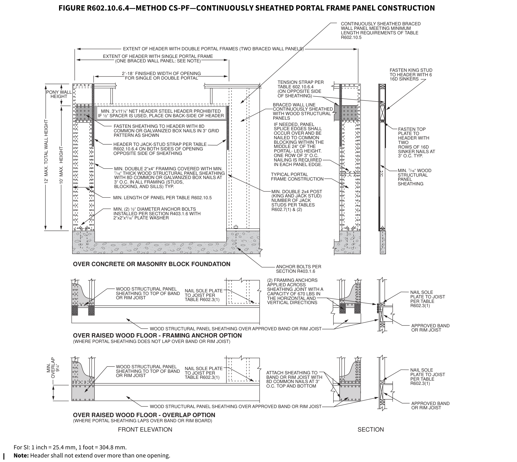 Open full-size illustration ↗
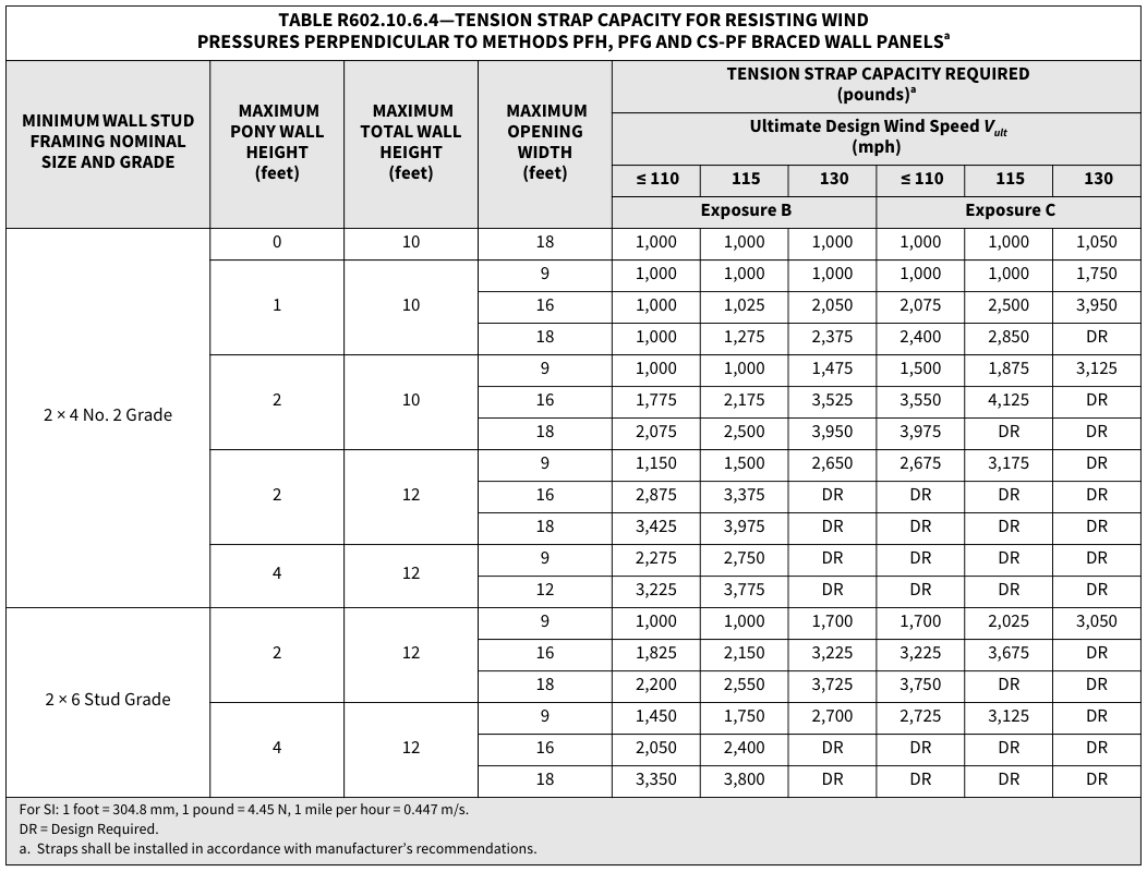 Open full-size table ↗
R602.10.6.5 Wall bracing for dwellings with stone and masonry veneer in Seismic Design…¶
R602.10.6.5 Wall bracing for dwellings with stone and masonry veneer in Seismic Design Categories D 0 , D 1 and D 2 . Townhouses in Seismic Design Categories D 0, D 1 and D 2 with stone or masonry veneer exceeding the first-story height shall be designed in accordance with accepted engineering practice.
One- and two-family dwellings in Seismic Design Category D 2 exceeding two stories and having stone or masonry veneer shall be designed in accordance with accepted engineering practice.
Where stone and masonry veneer are installed in accordance with Section R703.8, wall bracing on exterior braced wall lines and braced wall lines on the interior of the building, backing or perpendicular to and laterally supporting veneered walls shall comply with this section.
R602.10.6.5.1 Veneer on first story only.¶
Where dwellings in Seismic Design Categories D 0, D 1 and D 2 have stone or masonry veneer installed in accordance with Section R703.8 and the veneer does not exceed the first-story height, wall bracing shall be in accordance with Section R602.10, exclusive of Section R602.10.6.5.
R602.10.6.5.2 Veneer exceeding first-story height. Where detached one- or two-family dwellings in Seismic Design Categories D 0, D 1 and D 2 have stone or masonry veneer installed in accordance with Section R703.8, and the veneer exceeds the first-story height, wall bracing at exterior braced wall lines and braced wall lines on the interior of the building shall be constructed using Method BV-WSP in accordance with this section and Figure R602.10.6.5.2. Cripple walls shall not be permitted, and required interior braced wall lines shall be supported on continuous foundations.
FIGURE R602.10.6.5.2—METHOD BV-WSP—WALL BRACING FOR
DWELLINGS WITH STONE AND MASONRY VENEER IN SEISMIC DESIGN CATEGORIES D 0 , D 1 and D 2
EXTENT OF TOP STORY BRACED EXTENT OF WALL PANEL ALIGNED BRACED WALL PANELS
EDGE OF SHEATHING TO BRACED WALL PANEL END POST, TYP.
BRACED WALL PANEL
SINGLE-STORY HOLD-DOWN FORCE -TOP STORY
HOLD DOWNS ON SAME POST OR STUD TOP AND BOTTOM
CUMULATIVE HOLD-DOWN FORCE -MIDDLE STORY
BRACED WALL PANEL
CUMULATIVE HOLD-DOWN FORCE -BOTTOM STORY
HOLD-DOWN -SEE NOTE BELOW
EXTENT OF MIDDLE STORY BRACED WALL PANEL
EXTENT OF BOTTOM STORY BRACED WALL PANEL
GABLE END FRAMING
BRACED WALL PANEL
SINGLE-STORY HOLDDOWN FORCE-TOP STORY
BRACED WALL PANEL
HOLD DOWN -SEE NOTE BELOW
SINGLE-STORY HOLD-DOWN FORCE -MIDDLE STORY
BRACED WALL PANEL
SINGLE-STORY HOLDDOWN FORCE -BOTTOM STORY
CUMULATIVE HOLDDOWN FORCE -BOTTOM OF TWOSTORY
(a) Braced wall panels stacked (aligned story to story). Use cumulative hold-down force.
(b)
Braced wall panels mixed stacked and not stacked. Use hold-down force as noted.
Note: Hold downs should be strap ties, tension ties, or other approved hold-down devices and shall be installed in accordance with the manufacturer’s instructions.
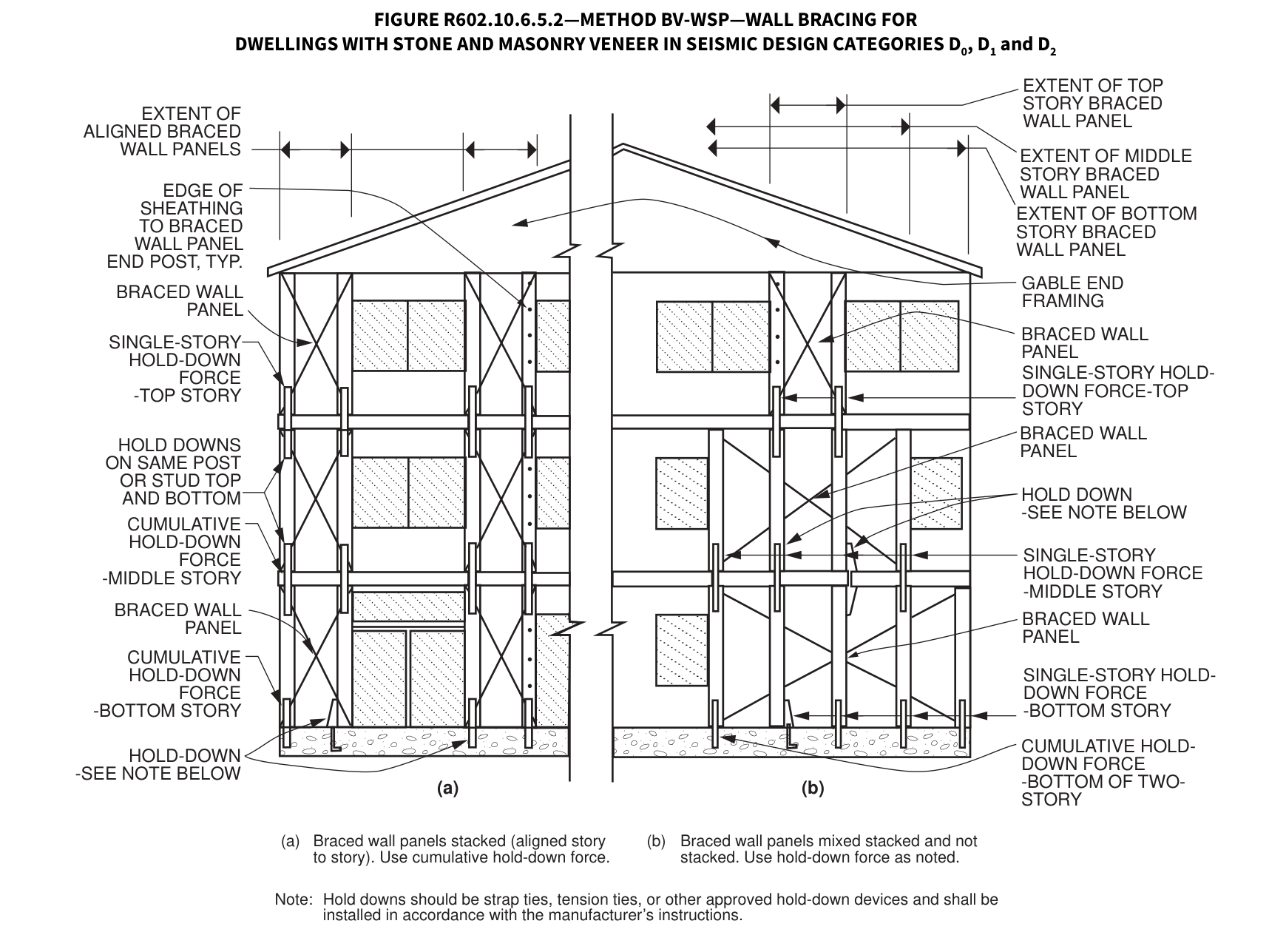 Open full-size illustration ↗
R602.10.6.5.3 Limited veneer exceeding first-story height.¶
Where detached one- or two-family dwellings in Seismic Design Categories D 0, D 1 and D 2 have exterior veneer installed in accordance with Section R703.8 and where brick veneer installed above the first-story height meets the following limitations, bracing in accordance with Method WSP or CS-WSP shall be permitted provided that the total length of braced wall panels specified by Table R602.10.3(3) is multiplied by 1.2 for each first- and second-story braced wall line.
- The dwelling does not extend more than two stories above grade plane.
- The veneer does not exceed 5 inches (127 mm) in thickness.
- The height of veneer on gable-end walls does not extend more than 8 feet (2438 mm) above the bearing wall top plate elevation.
- Where veneer is installed on multiple walls above the first story, the total area of the veneer on the second-story exterior walls shall not exceed 25 percent of the occupied second floor area.
- Where the veneer is installed on one entire second-story exterior wall, including walls on bay windows and similar appurtenances, brick veneer shall not be installed on any of the other walls on that floor.
R602.10.6.5.4 Length of bracing.¶
The length of bracing along each braced wall line shall be the greater of that required by the ultimate design wind speed and braced wall line spacing in accordance with Table R602.10.3(1) as adjusted by the factors in Table R602.10.3(2) or the seismic design category and braced wall line length in accordance either with Table R602.10.6.5.4 when using Method BV-WSP, or Table R602.10.3(3) as adjusted by the factors in Table R602.10.3(4) when using Method WSP or CS-WSP. Angled walls shall be permitted to be counted in accordance with Section R602.10.1.4, and braced wall panel location shall be in accordance with Section R602.10.2.2. Spacing between braced wall lines shall be in accordance with Table R602.10.1.3. The seismic adjustment factors in Table R602.10.3(4) shall not be applied to the length of bracing determined using Table R602.10.6.5.4, except that the bracing amount increase for braced wall line spacing greater than 25 feet (7620 mm) in accordance with Table R602.10.1.3 shall be required. The minimum total length of bracing in a braced wall line, after all adjustments have been taken, shall be not less than 48 inches (1219 mm) total.
TABLE R602.10.6.5.4—METHOD BV-WSP WALL BRACING REQUIREMENTSd¶
TABLE R602.10.6.5.4—METHOD BV-WSP WALL BRACING REQUIREMENTSd
| ** SEISMIC** DESIGN CATEGORY |
** STORY** | ** BRACED WALL LINE LENGTH (FEET)** | ** BRACED WALL LINE LENGTH (FEET)** | ** BRACED WALL LINE LENGTH (FEET)** | ** BRACED WALL LINE LENGTH (FEET)** | ** BRACED WALL LINE LENGTH (FEET)** | SINGLE-STORY HOLD-DOWN FORCE (pounds)b | CUMULATIVE HOLD-DOWN FORCE (pounds)c |
|---|---|---|---|---|---|---|---|---|
| ** SEISMIC** DESIGN CATEGORY |
** STORY** | ** 10** | ** 20** | ** 30** | ** 40** | ** 50** | SINGLE-STORY HOLD-DOWN FORCE (pounds)b | CUMULATIVE HOLD-DOWN FORCE (pounds)c |
| ** SEISMIC** DESIGN CATEGORY |
** STORY** | ** Minimum Total Length (feet) of Braced Wall** Panels Required Along each Braced Wall Line |
** Minimum Total Length (feet) of Braced Wall** Panels Required Along each Braced Wall Line |
** Minimum Total Length (feet) of Braced Wall** Panels Required Along each Braced Wall Line |
** Minimum Total Length (feet) of Braced Wall** Panels Required Along each Braced Wall Line |
** Minimum Total Length (feet) of Braced Wall** Panels Required Along each Braced Wall Line |
SINGLE-STORY HOLD-DOWN FORCE (pounds)b | CUMULATIVE HOLD-DOWN FORCE (pounds)c |
| D0 | One-story building (original diagram) | 4.0 | 7.0 | 10.5 | 14.0 | 17.5 | NA | — |
| D0 | Top story of a one-, two- or three-story building (original diagram) | 4.0 | 7.0 | 10.5 | 14.0 | 17.5 | 1,900 | — |
| D0 | First story of a two-story building or second story of a three-story building (original diagram) | 4.5 | 9.0 | 13.5 | 18.0 | 22.5 | 3,500 | 5,400 |
| D0 | First story of a three-story building (original diagram) | 6.0 | 12.0 | 18.0 | 24.0 | 30.0 | 3,500 | 8,900 |
| D1 | Top story of a one-, two- or three-story building (original diagram) | 4.5 | 9.0 | 13.5 | 18.0 | 22.5 | 2,100 | — |
| D1 | First story of a two-story building or second story of a three-story building (original diagram) | 4.5 | 9.0 | 13.5 | 18.0 | 22.5 | 3,700 | 5,800 |
| D1 | First story of a three-story building (original diagram) | 6.0 | 12.0 | 18.0 | 24.0 | 30.0 | 3,700 | 9,500 |
| CONTINUOUSLY SHEATHED BRACED WALL LINE RETURN PANEL BRACED WALL PANEL AT END OF BRACED WALL LINE END CONDITION 1 |
CONTINUOUSLY SHEATHED BRACED WALL LINE HOLD- DOWN DEVICE BRACED WALL PANEL AT END OF BRACED WALL LINE END CONDITION 2 |
|---|---|
| 48″ MINIMUM BRACED WALL PANEL AT END OF BRACED WALL LINE CONTINUOUSLY SHEATHED BRACED WALL LINE END CONDITION 3 |
FIRST BRACED WALL PANEL RETURN PANEL * SEE REQUIREMENTS D* 10′ MAX CONTINUOUSLY SHEATHED BRACED WALL LINE END CONDITION 4 |
| HOLD-DOWN DEVICE FIRST BRACED WALL PANEL CONTINUOUSLY SHEATHED BRACED WALL LINE END CONDITION 5 10′ MAX 10′ MAX |
REQUIREMENTS Return panel: 24″ for braced wall lines sheathed with wood structural panels 32″ for braced wall lines sheathed with structural fiberboard 24″ for braced wall lines sheathed with wood structural panels 32″ for braced wall lines sheathed with structural fiberboard Distance D: 800 lbs capacity fastened to the edge of the braced wall panel closest to the corner and to the foundation or floor framing below Hold-down device: |
TABLE R602.10.6.5.4—METHOD BV-WSP WALL BRACING REQUIREMENTSd—continued
| ** SEISMIC** DESIGN CATEGORY |
** STORY** | ** BRACED WALL LINE LENGTH (FEET)** | ** BRACED WALL LINE LENGTH (FEET)** | ** BRACED WALL LINE LENGTH (FEET)** | ** BRACED WALL LINE LENGTH (FEET)** | ** BRACED WALL LINE LENGTH (FEET)** | SINGLE-STORY HOLD-DOWN FORCE (pounds)b | CUMULATIVE HOLD-DOWN FORCE (pounds)c |
|---|---|---|---|---|---|---|---|---|
| ** SEISMIC** DESIGN CATEGORY |
** STORY** | ** 10** | ** 20** | ** 30** | ** 40** | ** 50** | SINGLE-STORY HOLD-DOWN FORCE (pounds)b | CUMULATIVE HOLD-DOWN FORCE (pounds)c |
| ** SEISMIC** DESIGN CATEGORY |
** STORY** | ** Minimum Total Length (feet) of Braced Wall** Panels Required Along each Braced Wall Line |
** Minimum Total Length (feet) of Braced Wall** Panels Required Along each Braced Wall Line |
** Minimum Total Length (feet) of Braced Wall** Panels Required Along each Braced Wall Line |
** Minimum Total Length (feet) of Braced Wall** Panels Required Along each Braced Wall Line |
** Minimum Total Length (feet) of Braced Wall** Panels Required Along each Braced Wall Line |
SINGLE-STORY HOLD-DOWN FORCE (pounds)b | CUMULATIVE HOLD-DOWN FORCE (pounds)c |
| D2 a |
Top story of a one- or two-story building (original diagram) | 5.5 | 11.0 | 16.5 | 22.0 | 27.5 | 2,300 | — |
| D2 a |
First story of a two-story building (original diagram) | 5.5 | 11.0 | 16.5 | 22.0 | 27.5 | 3,900 | 6,200 |
| D2 a |
Three-story dwelling |
NP | NP | NP | NP | NP | NA | NA |
R602.10.7 Ends of braced wall lines with continuous sheathing. Each end of a braced wall line with continuous sheathing shall
have one of the conditions shown in Figure R602.10.7.
FIGURE R602.10.7—END CONDITIONS FOR BRACED WALL LINES WITH CONTINUOUS SHEATHING
For SI: 1 inch = 25.4 mm, 1 foot = 304.8 mm, 1 pound = 4.45 N.
END CONDITION 1
CONTINUOUSLY SHEATHED
BRACED WALL LINE
RETURN
PANEL
HOLD-
DOWN
DEVICE
HOLD-DOWN
DEVICE
BRACED WALL PANEL AT
END OF BRACED WALL LINE
BRACED WALL PANEL AT
END OF BRACED WALL LINE
FIRST BRACED
WALL PANEL
RETURN
PANEL
* SEE REQUIREMENTS
48″ MINIMUM BRACED WALL PANEL
AT END OF BRACED WALL LINE
FIRST BRACED
WALL PANEL
D*
10′ MAX
CONTINUOUSLY SHEATHED
BRACED WALL LINE
CONTINUOUSLY SHEATHED
BRACED WALL LINE
CONTINUOUSLY SHEATHED
BRACED WALL LINE
CONTINUOUSLY SHEATHED
BRACED WALL LINE
END CONDITION 2
END CONDITION 3
END CONDITION 5
END CONDITION 4
REQUIREMENTS
Return panel: 24″ for braced wall lines sheathed with
wood structural panels
32″ for braced wall lines sheathed with
structural fiberboard
24″ for braced wall lines sheathed with
wood structural panels
32″ for braced wall lines sheathed with
structural fiberboard
Distance D:
800 lbs capacity fastened to the edge of the
braced wall panel closest to the corner and
to the foundation or floor framing below
Hold-down
device:
10′ MAX
10′ MAX
32″ for braced wall lines sheathed with
structural fiberboard
24″ for braced wall lines sheathed with
wood structural panels
32″ for braced wall lines sheathed with
structural fiberboard
Distance D:
800 lbs capacity fastened to the edge of the
braced wall panel closest to the corner and
to the foundation or floor framing below
Hold-down
device:
10′ MAX
10′ MAX|R602.10.7 Ends of braced wall lines with continuous sheathing. Each end of a braced wall line with continuous sheathing shall
have one of the conditions shown in Figure R602.10.7.
FIGURE R602.10.7—END CONDITIONS FOR BRACED WALL LINES WITH CONTINUOUS SHEATHING
For SI: 1 inch = 25.4 mm, 1 foot = 304.8 mm, 1 pound = 4.45 N.
END CONDITION 1
CONTINUOUSLY SHEATHED
BRACED WALL LINE
RETURN
PANEL
HOLD-
DOWN
DEVICE
HOLD-DOWN
DEVICE
BRACED WALL PANEL AT
END OF BRACED WALL LINE
BRACED WALL PANEL AT
END OF BRACED WALL LINE
FIRST BRACED
WALL PANEL
RETURN
PANEL
* SEE REQUIREMENTS
48″ MINIMUM BRACED WALL PANEL
AT END OF BRACED WALL LINE
FIRST BRACED
WALL PANEL
D*
10′ MAX
CONTINUOUSLY SHEATHED
BRACED WALL LINE
CONTINUOUSLY SHEATHED
BRACED WALL LINE
CONTINUOUSLY SHEATHED
BRACED WALL LINE
CONTINUOUSLY SHEATHED
BRACED WALL LINE
END CONDITION 2
END CONDITION 3
END CONDITION 5
END CONDITION 4
REQUIREMENTS
Return panel: 24″ for braced wall lines sheathed with
wood structural panels
32″ for braced wall lines sheathed with
structural fiberboard
24″ for braced wall lines sheathed with
wood structural panels
32″ for braced wall lines sheathed with
structural fiberboard
Distance D:
800 lbs capacity fastened to the edge of the
braced wall panel closest to the corner and
to the foundation or floor framing below
Hold-down
device:
10′ MAX
10′ MAX|R602.10.7 Ends of braced wall lines with continuous sheathing. Each end of a braced wall line with continuous sheathing shall
have one of the conditions shown in Figure R602.10.7.
FIGURE R602.10.7—END CONDITIONS FOR BRACED WALL LINES WITH CONTINUOUS SHEATHING
For SI: 1 inch = 25.4 mm, 1 foot = 304.8 mm, 1 pound = 4.45 N.
END CONDITION 1
CONTINUOUSLY SHEATHED
BRACED WALL LINE
RETURN
PANEL
HOLD-
DOWN
DEVICE
HOLD-DOWN
DEVICE
BRACED WALL PANEL AT
END OF BRACED WALL LINE
BRACED WALL PANEL AT
END OF BRACED WALL LINE
FIRST BRACED
WALL PANEL
RETURN
PANEL
* SEE REQUIREMENTS
48″ MINIMUM BRACED WALL PANEL
AT END OF BRACED WALL LINE
FIRST BRACED
WALL PANEL
D*
10′ MAX
CONTINUOUSLY SHEATHED
BRACED WALL LINE
CONTINUOUSLY SHEATHED
BRACED WALL LINE
CONTINUOUSLY SHEATHED
BRACED WALL LINE
CONTINUOUSLY SHEATHED
BRACED WALL LINE
END CONDITION 2
END CONDITION 3
END CONDITION 5
END CONDITION 4
REQUIREMENTS
Return panel: 24″ for braced wall lines sheathed with
wood structural panels
32″ for braced wall lines sheathed with
structural fiberboard
24″ for braced wall lines sheathed with
wood structural panels
32″ for braced wall lines sheathed with
structural fiberboard
Distance D:
800 lbs capacity fastened to the edge of the
braced wall panel closest to the corner and
to the foundation or floor framing below
Hold-down
device:
10′ MAX
10′ MAX|R602.10.7 Ends of braced wall lines with continuous sheathing. Each end of a braced wall line with continuous sheathing shall
have one of the conditions shown in Figure R602.10.7.
FIGURE R602.10.7—END CONDITIONS FOR BRACED WALL LINES WITH CONTINUOUS SHEATHING
For SI: 1 inch = 25.4 mm, 1 foot = 304.8 mm, 1 pound = 4.45 N.
END CONDITION 1
CONTINUOUSLY SHEATHED
BRACED WALL LINE
RETURN
PANEL
HOLD-
DOWN
DEVICE
HOLD-DOWN
DEVICE
BRACED WALL PANEL AT
END OF BRACED WALL LINE
BRACED WALL PANEL AT
END OF BRACED WALL LINE
FIRST BRACED
WALL PANEL
RETURN
PANEL
* SEE REQUIREMENTS
48″ MINIMUM BRACED WALL PANEL
AT END OF BRACED WALL LINE
FIRST BRACED
WALL PANEL
D*
10′ MAX
CONTINUOUSLY SHEATHED
BRACED WALL LINE
CONTINUOUSLY SHEATHED
BRACED WALL LINE
CONTINUOUSLY SHEATHED
BRACED WALL LINE
CONTINUOUSLY SHEATHED
BRACED WALL LINE
END CONDITION 2
END CONDITION 3
END CONDITION 5
END CONDITION 4
REQUIREMENTS
Return panel: 24″ for braced wall lines sheathed with
wood structural panels
32″ for braced wall lines sheathed with
structural fiberboard
24″ for braced wall lines sheathed with
wood structural panels
32″ for braced wall lines sheathed with
structural fiberboard
Distance D:
800 lbs capacity fastened to the edge of the
braced wall panel closest to the corner and
to the foundation or floor framing below
Hold-down
device:
10′ MAX
10′ MAX|SINGLE-STORY HOLD-DOWN FORCE (pounds)b|CUMULATIVE HOLD-DOWN FORCE (pounds)c|
TABLE R602.10.6.5.4—METHOD BV-WSP WALL BRACING REQUIREMENTSd—continued
| 2025 CALIFORNIA RESIDENTIAL CODE 6-45 |
2025 CALIFORNIA RESIDENTIAL CODE 6-45 |
2025 CALIFORNIA RESIDENTIAL CODE 6-45 |
2025 CALIFORNIA RESIDENTIAL CODE 6-45 |
2025 CALIFORNIA RESIDENTIAL CODE 6-45 |
2025 CALIFORNIA RESIDENTIAL CODE 6-45 |
2025 CALIFORNIA RESIDENTIAL CODE 6-45 |
SINGLE-STORY HOLD-DOWN FORCE (pounds)b | CUMULATIVE HOLD-DOWN FORCE (pounds)c |
|---|
For SI: 1 inch = 25.4 mm, 1 foot = 304.8 mm, 1 pound per square foot = 0.479 kPa, 1 pound-force = 4.448 N. NP = Not Permitted. NA = Not Applicable. a. One- and two-family dwellings in Seismic Design Category D2 exceeding two stories shall be designed in accordance with accepted engineering practices. b. Hold-down force is minimum allowable stress design load for connector providing uplift tie from wall framing at end of braced wall panel at the noted story to wall framing at end of braced wall panel at the story below, or to foundation or foundation wall. Use single-story hold-down force where edges of braced wall panels do not align; a continuous load path to the foundation shall be maintained. c. Where hold-down connectors from stories above align with stories below, use cumulative hold-down force to size middle- and bottom-story hold-down connectors. d. Interpolation between braced wall lengths is permitted.
WALL CONSTRUCTION
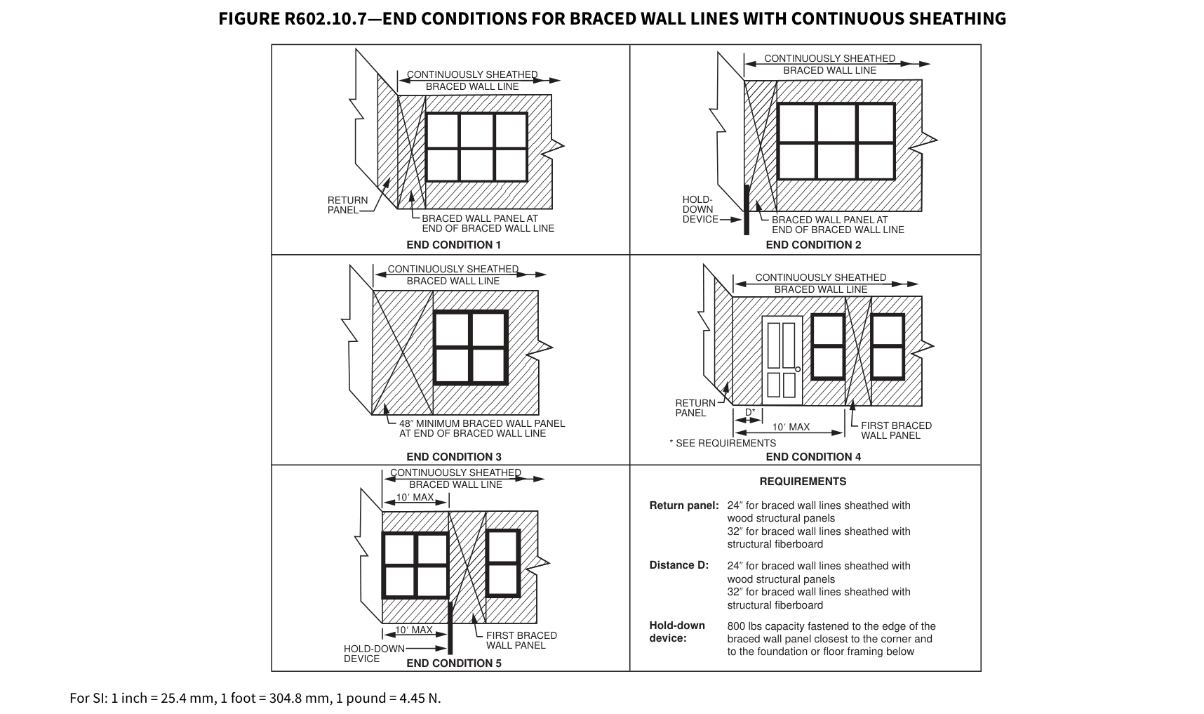 Open full-size illustration ↗
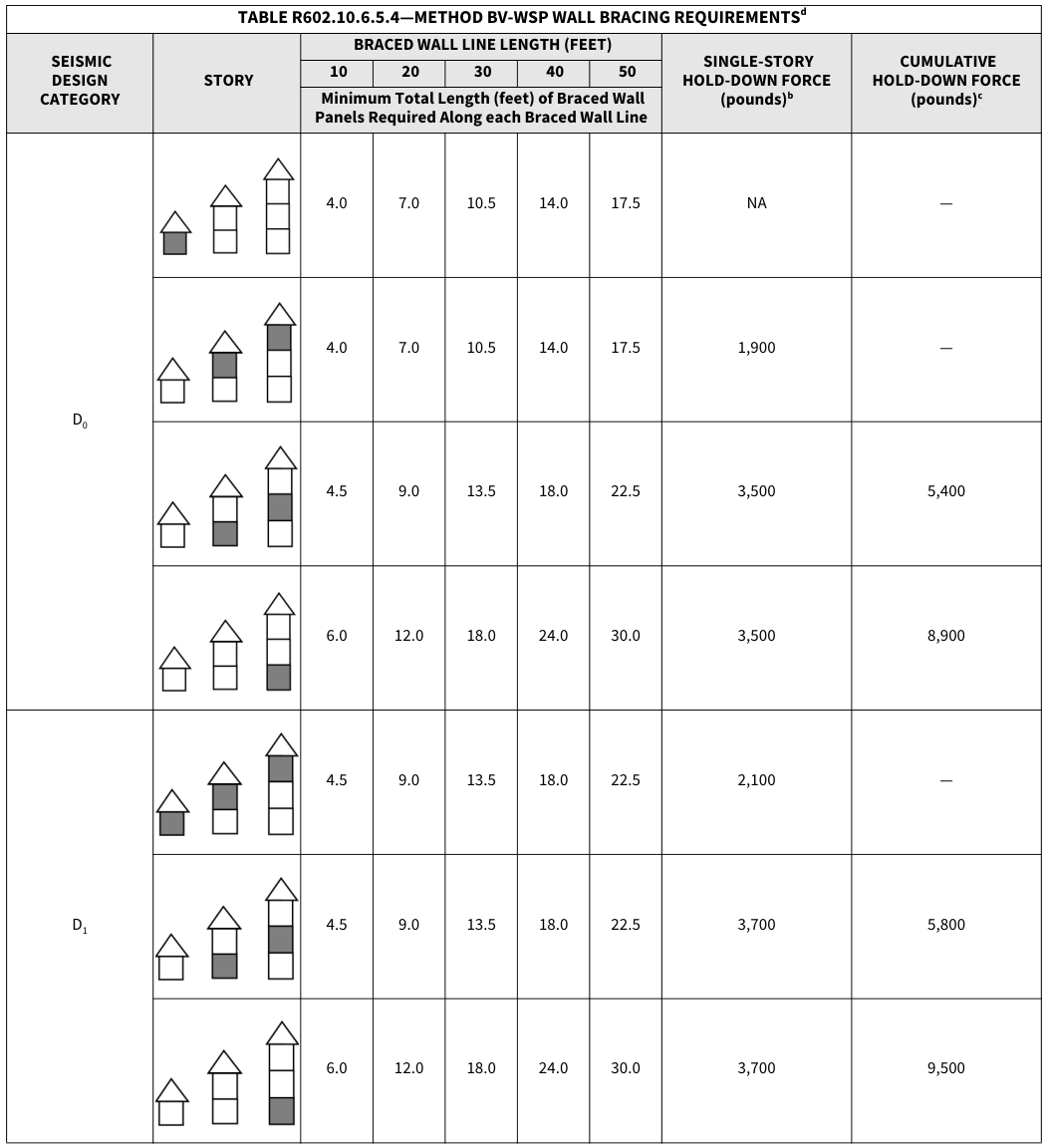 Open full-size table ↗
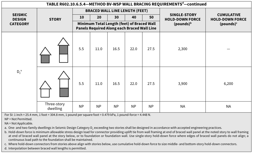 Open full-size table ↗
R602.10.8 Braced wall panel connections.¶
Braced wall panels shall be connected to floor framing or foundations as follows:
Where joists are perpendicular to a braced wall panel above or below, a rim joist, band joist or blocking shall be provided along the entire length of the braced wall panel in accordance with Figure R602.10.8(1). Fastening of top and bottom wall plates to framing, rim joist, band joist or blocking shall be in accordance with Table R602.3(1).
Where joists are parallel to a braced wall panel above or below, a rim joist, end joist or other parallel framing member shall be provided directly above and below the braced wall panel in accordance with Figure R602.10.8(2). Where a parallel framing member cannot be located directly above and below the panel, full-depth blocking at 16-inch (406 mm) spacing shall be provided between the parallel framing members to each side of the braced wall panel in accordance with Figure R602.10.8(2). Fastening of blocking and wall plates shall be in accordance with Table R602.3(1) and Figure R602.10.8(2).
Connections of braced wall panels to concrete or masonry shall be in accordance with Section R403.1.6.
FIGURE R602.10.8(1)—BRACED WALL PANEL CONNECTION WHEN PERPENDICULAR TO FLOOR/CEILING FRAMING
PERPENDICULAR FRAMING
8d @ 6 ″ O.C. ALONG BRACED WALL PANEL
3-16d @ 16 ″ O.C. ALONG 3-16d @ 16 ″ O.C. ALONG BRACED WALL PANEL BRACED WALL PANEL
PERPENDICULAR FRAMING
| L-HEIGHT BLOCKING | |
|---|---|
| -HEIGHT BLOCKING TINUOUS ALONG LENGTH RACED WALL PANEL |
|
| AMING | |
| 3-16d @ 16″ O.C. BRACED WALL P BRACED WALL 8d @ 6″ O.C. ALO BRACED WALL P |
|
| MING | |
CONTINUOUS RIM CONTINUOUS ALONG LENGTH OR BAND JOIST OF BRACED WALL PANEL
For SI: 1 inch = 25.4 mm.
| CONTINUOUS RIM OR BAND JOIST |
|
|---|---|
| PERP | |
| BRACED WALL PANEL 3-16d @ 16″ O.C. ALONG BRACED WALL PANEL 8d @ 6″ O.C. ALONG BRACED WALL PANEL |
|
| PERPE | |
FIGURE R602.10.8(2)—BRACED WALL PANEL CONNECTION WHEN PARALLEL TO FLOOR/CEILING FRAMING
CONTINUOUS RIM ADDITIONAL FRAMING OR END JOIST MEMBER DIRECTLY ABOVE
FULL-HEIGHT BLOCKING
BRACED WALL PANEL BRACED WALL PANEL
3-16d @ 16BRACED WALL PANEL ″ O.C. ALONG 3-16d @ 16 ″ O.C. ALONG 3-16d AT EACH BRACED WALL PANEL BLOCKING MEMBER
2-16d NAILS EACH SIDE
FULL-HEIGHT BLOCKING @ 16 ″ O.C. ALONG BRACED WALL PANEL
| ADDITIONAL | |
|---|---|
| ADDITIONAL MEMBER DIR BRACED WA |
ADDITIONAL MEMBER DIR BRACED WA |
| BRACED W 3-16d @ 16″ O BRACED WAL 8d @ 6″ O.C. BRACED WA |
|
| ADDITIONA | ADDITIONA |
CONTINUOUS RIM OR END JOIST
ADDITIONAL FRAMING MEMBER DIRECTLY BELOW BRACED WALL PANEL
| CONTINUO OR END JO |
||
|---|---|---|
| BRACED W 3-16d @ 16″ O BRACED WAL 8d @ 6″ O.C. BRACED WAL |
||
| CONT |
CONT |
|
For SI: 1 inch = 25.4 mm.
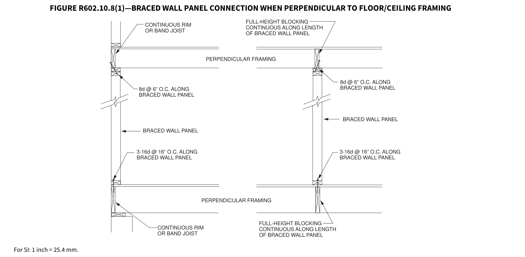 Open full-size illustration ↗
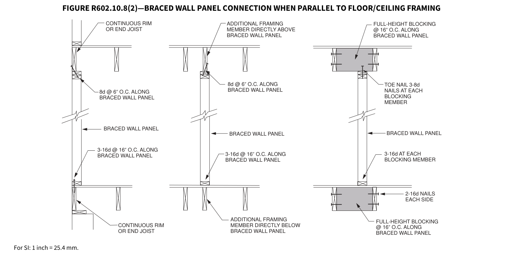 Open full-size illustration ↗
R602.10.8.1 Braced wall panel connections for Seismic Design Categories D 0, D 1 and D 2.¶
R602.10.8.1 Braced wall panel connections for Seismic Design Categories D 0 , D 1 and D 2 . Braced wall panels shall be fastened to required foundations in accordance with Section R602.11.1, and top plate lap splices shall be face-nailed with not less than eight 16d nails on each side of the splice.
R602.10.8.2 Connections to roof framing. Top plates of exterior braced wall panels shall be attached to rafters or roof trusses above in accordance with Table R602.3(1) and this section. Where required by this section, blocking between rafters or roof trusses shall be attached to top plates of braced wall panels and to rafters and roof trusses in accordance with Table R602.3(1). A continuous band, rim or header joist or roof truss parallel to the braced wall panels shall be permitted to replace the blocking required by this section. Blocking shall not be required over openings in continuously sheathed braced wall lines. In addition to the requirements of this section, lateral support shall be provided for rafters and ceiling joists in accordance with Section R802.8 and for trusses in accordance with Section R802.10.3. Roof ventilation shall be provided in accordance with Section R806.1.
- For Seismic Design Categories A, B and C where the distance from the top of the braced wall panel to the top of the rafters or roof trusses above is 9 1/4 inches (235 mm) or less, blocking between rafters or roof trusses shall not be required. Where the distance from the top of the braced wall panel to the top of the rafters or roof trusses above is between 9 1/4 inches (235 mm) and 15 1/4 inches (387 mm), blocking between rafters or roof trusses shall be provided above the braced wall panel in accordance with Figure R602.10.8.2(1).
Exception: Where the outside edge of truss vertical web members aligns with the outside face of the wall studs below, wood structural panel sheathing extending above the top plate as shown in Figure R602.10.8.2(3) shall be permitted to be fastened to each truss web with three-8d nails (2 1/2 inches × 0.131 inch) and blocking between the trusses shall not be required. 2. For Seismic Design Categories D 0, D 1 and D 2, where the distance from the top of the braced wall panel to the top of the rafters or roof trusses is 15 1/4 inches (387 mm) or less, blocking between rafters or roof trusses shall be provided above the braced wall panel in accordance with Figure R602.10.8.2(1). 3. Where the distance from the top of the braced wall panel to the top of rafters or roof trusses exceeds 15 1/4 inches (387 mm), the top plates of the braced wall panel shall be connected to perpendicular rafters or roof trusses above in accordance with one or more of the following methods: 3.1. Soffit blocking panels constructed in accordance with Figure R602.10.8.2(2). 3.2. Vertical blocking panels constructed in accordance with Figure R602.10.8.2(3). 3.3. Blocking panels provided by the roof truss manufacturer and designed in accordance with Section R802. 3.4. Blocking, blocking panels or other methods of lateral load transfer designed in accordance with the AWC
FIGURE R602.10.8.2(1)—BRACED WALL PANEL CONNECTION TO PERPENDICULAR RAFTERS
SOLID BLOCKING BETWEEN RAFTERS ATTACHED TO TOP PLATES WITH 8d @ 6 ″ O.C. ALONG LENGTH OF BRACED WALL PANEL
For SI: 1 inch = 25.4 mm.
FIGURE R602.10.8.2(2)—BRACED WALL PANEL CONNECTION OPTION TO PERPENDICULAR RAFTERS OR ROOF TRUSSES
For SI: 1 inch = 25.4 mm, 1 foot = 304.8 mm. a. Methods of bracing shall be as described in Section R602.10.4.
FIGURE R602.10.8.2(3)—BRACED WALL PANEL CONNECTION OPTION TO PERPENDICULAR RAFTERS OR ROOF TRUSSES
WHERE AIR GAP AT TOP IS NOT USED, CENTER W/3 AVAILABLE FOR VENT HOLES
| W | ||||||||||
|---|---|---|---|---|---|---|---|---|---|---|
| ROOF SHEATHING | ||||||
|---|---|---|---|---|---|---|
| BRACED WALL PANEL 2x BLK’G VENTING A BRACING a EDGE NAILING PER TABLE R602.3(1) (TYP) 2 MAX OPEN ″ ROOF TRUSSES PER R802.10 |
||||||
| ROOF TRUSSES PER R802.10 |
2x BLK’G |
|||||
| ROOF TRUSSES PER R802.10 |
BRA |
BRA |
BRA |
|||
| ROOF TRUSSES PER R802.10 |
BRA |
BRA |
BRA |
SECTION ELEVATION A B
For SI: 1 inch = 25.4 mm, 1 foot =304.8 mm a. Methods of bracing shall be as described in Section R602.10.4.
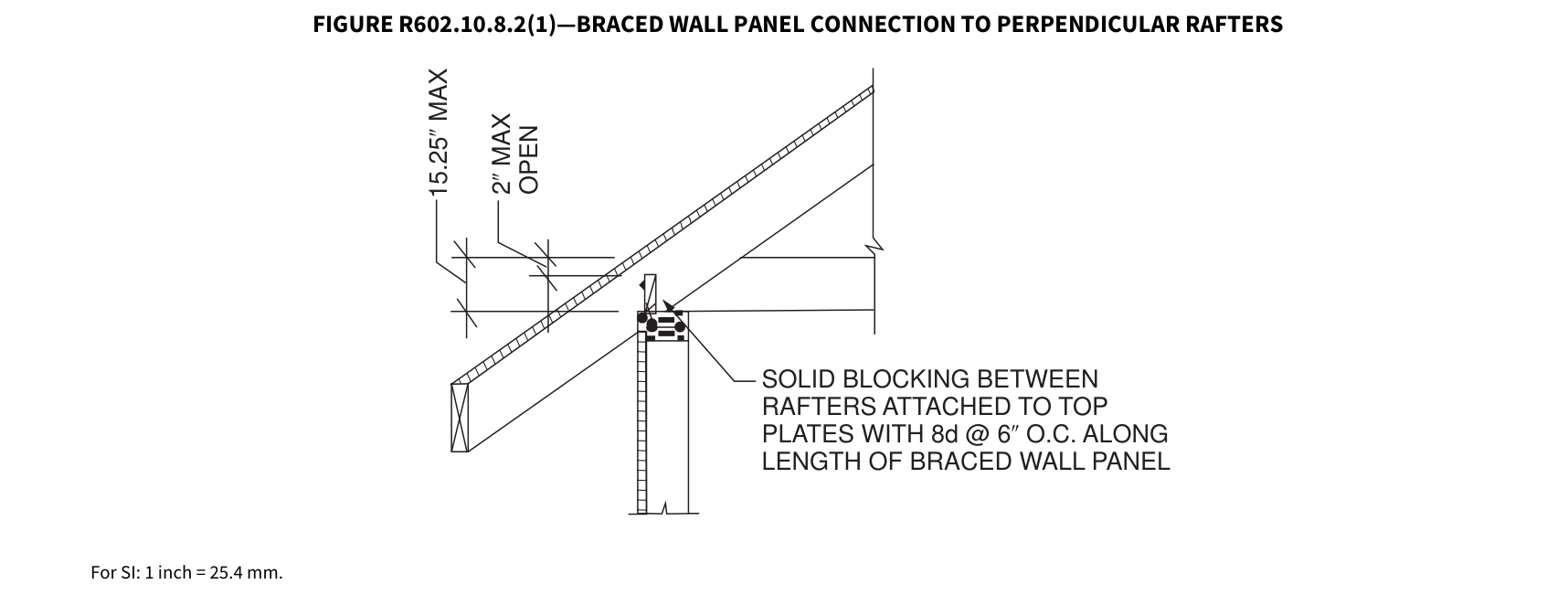 Open full-size illustration ↗
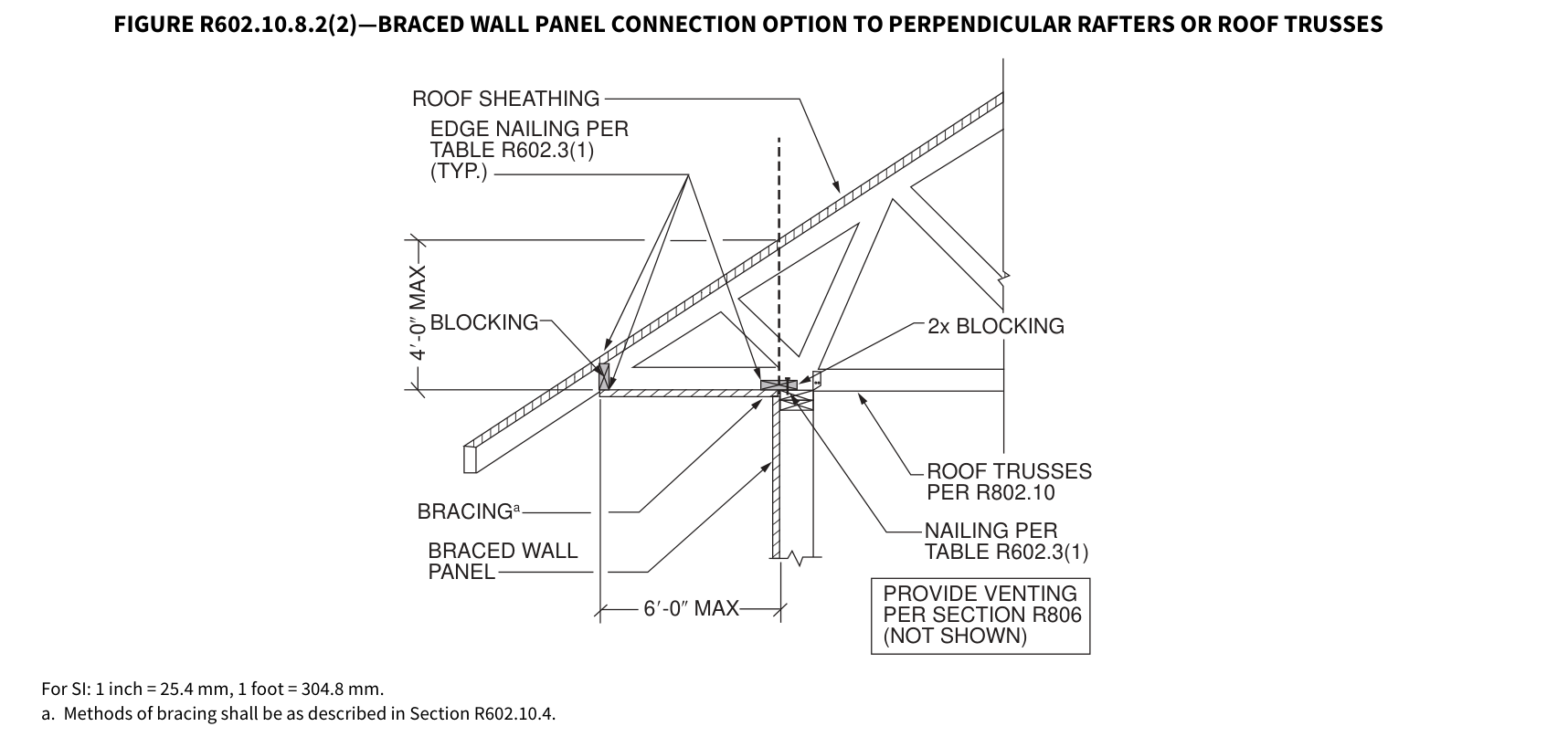 Open full-size illustration ↗
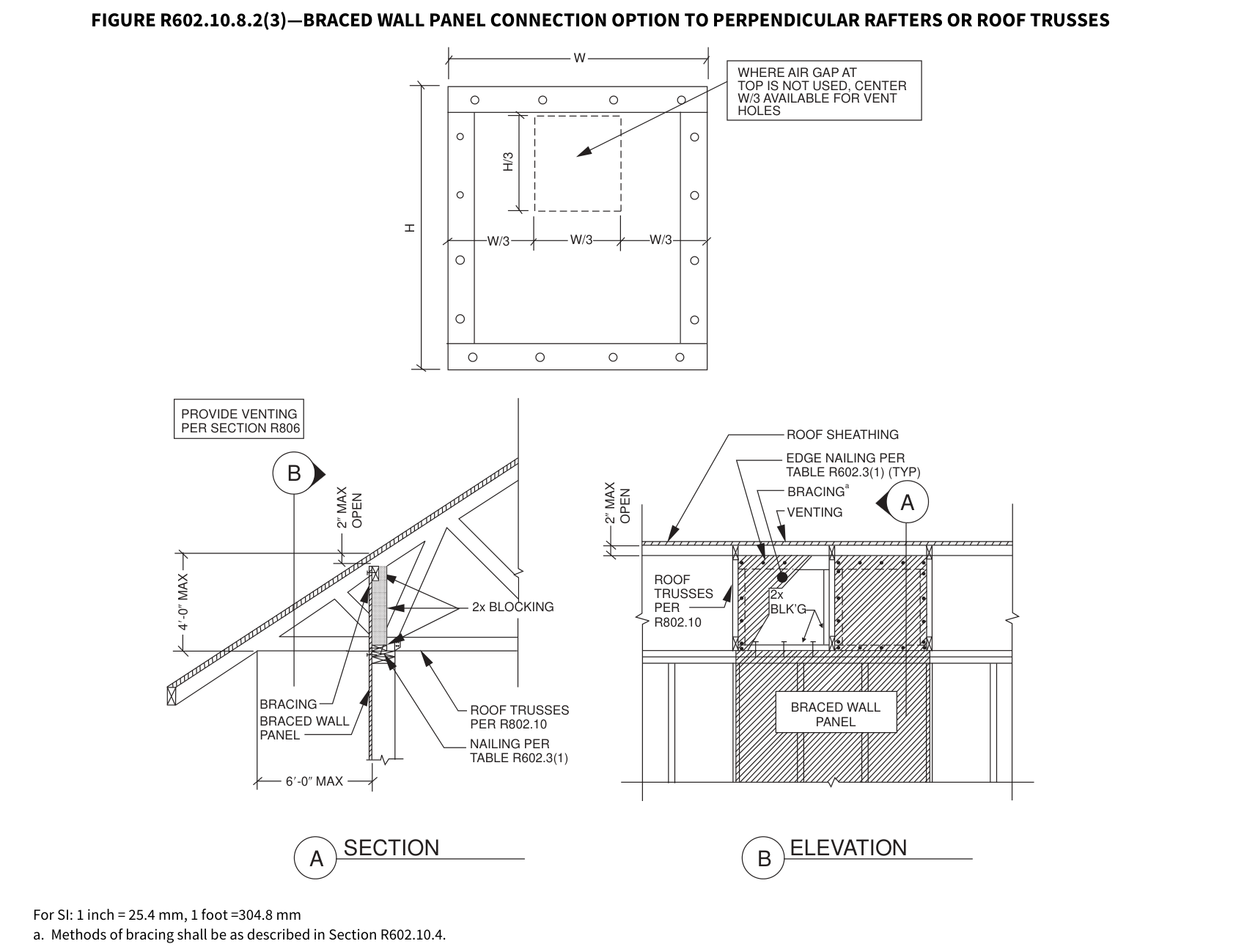 Open full-size illustration ↗
R602.10.9 Braced wall panel support.¶
Braced wall panel support shall be provided as follows:
- Cantilevered floor joists complying with Section R502.3.3 shall be permitted to support braced wall panels.
- Raised floor system post or pier foundations supporting braced wall panels shall be designed in accordance with accepted engineering practice.
- Masonry stem walls with a length of 48 inches (1219 mm) or less supporting braced wall panels shall be reinforced in accordance with Figure R602.10.9. Masonry stem walls with a length greater than 48 inches (1219 mm) supporting braced wall panels shall be constructed in accordance with Section R403.1 Methods ABW and PFH shall not be permitted to attach to masonry stem walls.
- Concrete stem walls with a length of 48 inches (1219 mm) or less, greater than 12 inches (305 mm) tall and less than 6 inches (152 mm) thick shall have reinforcement sized and located in accordance with Figure R602.10.9.
FIGURE R602.10.9—MASONRY STEM WALLS SUPPORTING BRACED WALL PANELS
| 48″ OR LESS | |||||
|---|---|---|---|---|---|
| 24″ MAX | |||||
| 24″ MAX | |||||
| 24″ MAX | |||||
| 24″ MAX | |||||
| 24″ MAX |
| 48″ OR LESS | ||||||
|---|---|---|---|---|---|---|
| 48″ MAXIMUM | ||||||
| 48″ MAXIMUM | ||||||
| 48″ MAXIMUM | ||||||
| 48″ MAXIMUM | ||||||
| 48″ MAXIMUM | ||||||
| 48″ MAXIMUM |
3 ″ COVER
| S SHALL BE ANCHOR |
FAC OPT |
E BRICK IONAL |
||||
| S SHALL BE ANCHOR |
FAC OPT |
E BRICK IONAL |
||||
| S SHALL BE ANCHOR |
FAC OPT |
E BRICK IONAL |
||||
| S SHALL BE ANCHOR |
||||||
| CUT WASHERS | 8″ MIN. | 8″ MIN. | 8″ MIN. | 8″ MIN. | 8″ MIN. | |
| CUT WASHERS | 8″ MIN. | 8″ MIN. | 8″ MIN. |
OPTIONAL STEM WALL REINFORCEMENT TYPICAL STEM WALL SECTION
NOTE: GROUT BOND BEAMS AND ALL CELLS THAT CONTAIN REBAR, THREADED RODS AND ANCHOR BOLTS.
For SI: 1 inch = 25.4 mm.
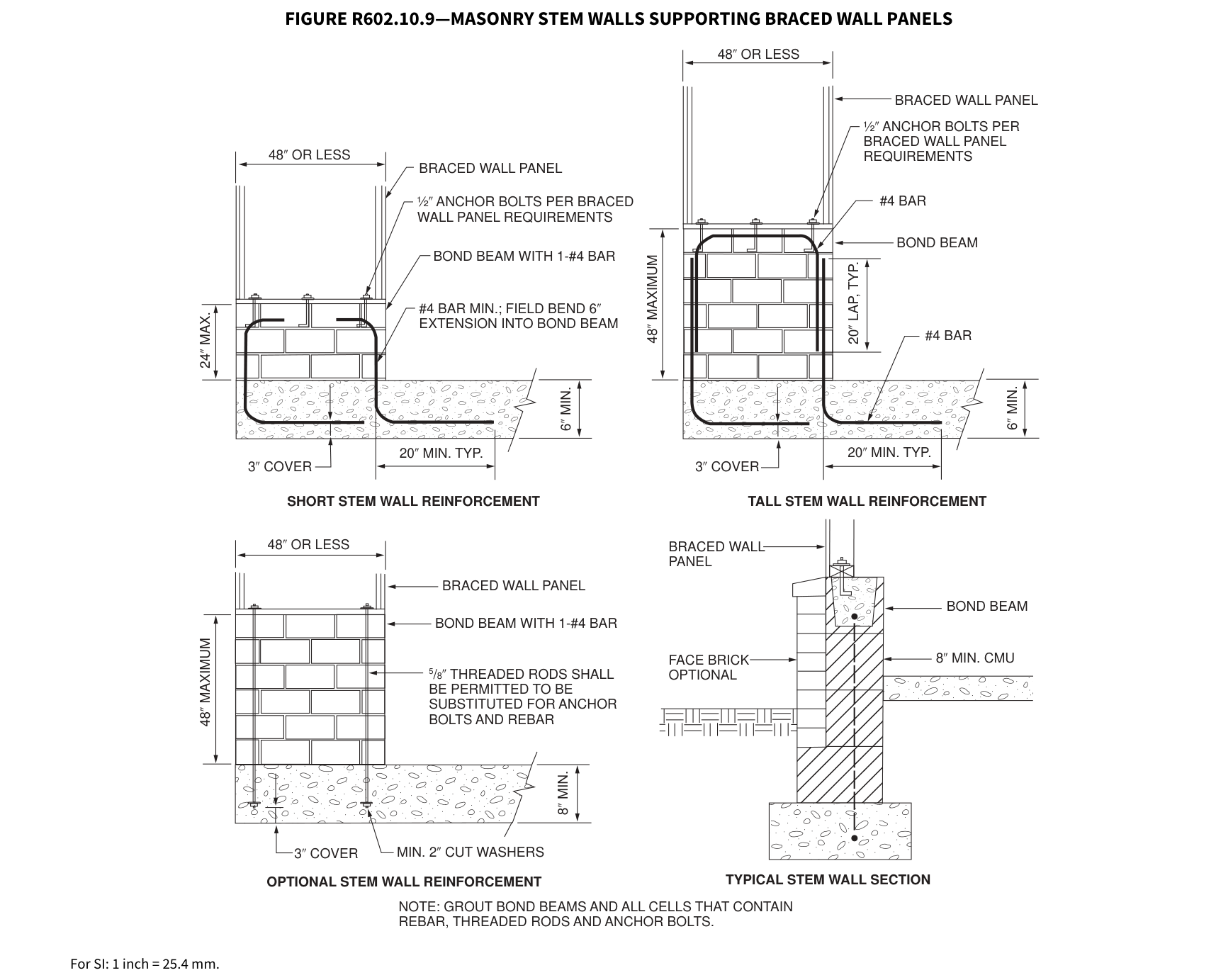 Open full-size illustration ↗
R602.10.9.1 Braced wall panel support for Seismic Design Categories D 0, D 1 and D 2.¶
R602.10.9.1 Braced wall panel support for Seismic Design Categories D 0 , D 1 and D 2 . In Seismic Design Categories D 0, D 1 and D 2, braced wall panel footings shall be as specified in Section R403.1.2.
R602.10.10 Cripple wall bracing. Cripple walls shall be constructed in accordance with Section R602.9 and braced in accordance with this section. Cripple walls shall be braced with the length and method of bracing used for the wall above in accordance with Tables R602.10.3(1) and R602.10.3(3), and the applicable adjustment factors in Table R602.10.3(2) or R602.10.3(4), respectively, except that the length of cripple wall bracing shall be multiplied by a factor of 1.15. Where gypsum wall board is not used on the inside of the cripple wall bracing, the length adjustments for the elimination of the gypsum wallboard, or equivalent, shall be applied as directed in Tables R602.10.3(2) and R602.10.3(4) to the length of cripple wall bracing required. This adjustment shall be taken in addition to the 1.15 increase.
R602.10.10.1 Cripple wall bracing for Seismic Design Categories D 0 and D 1 and…¶
In addition to the requirements in Section R602.10.10, cripple wall bracing shall be limited to methods WSP and CS-WSP, and the distance between adjacent edges of braced wall panels for cripple walls along a braced wall line shall be 14 feet (4267 mm) maximum.
Where braced wall lines at interior walls are not supported on a continuous foundation below, the adjacent parallel cripple walls, where provided, shall be braced with Method WSP or Method CS-WSP in accordance with Section R602.10.4. The length of bracing required in accordance with Table R602.10.3(3) for the cripple walls shall be multiplied by 1.5. Where the cripple walls do not have sufficient length to provide the required bracing, the spacing of panel edge fasteners shall be reduced to 4 inches (102 mm) on center and the required bracing length adjusted by 0.7. If the required length can still not be provided, the cripple wall shall be designed in accordance with accepted engineering practice.
R602.10.10.2 Cripple wall bracing for Seismic Design Category D 2.¶
R602.10.10.2 Cripple wall bracing for Seismic Design Category D 2 . In Seismic Design Category D 2, cripple walls shall be braced in accordance with Tables R602.10.3(3) and R602.10.3(4).
R602.10.10.3 Redesignation of cripple walls. Where all cripple wall segments along a braced wall line do not exceed 48 inches (1219 mm) in height, the cripple walls shall be permitted to be redesignated as a first-story wall for purposes of determining wall bracing requirements. Where any cripple wall segment in a braced wall line exceeds 48 inches (1219 mm) in height, the entire cripple wall shall be counted as an additional story. If the cripple walls are redesignated, the stories above the redesignated story shall be counted as the second and third stories, respectively.
R602.11 Wall anchorage.¶
Braced wall line sills shall be anchored to concrete or masonry foundations in accordance with Sections R403.1.6 and R602.11.1.
R602.11.1 Wall anchorage for all buildings in Seismic Design Categories D 0 , D 1 and D 2 and townhouses in Seismic Design Category C. Plate washers, not less than 0.229 inch by 3 inches by 3 inches (5.8 mm by 76 mm by 76 mm) in size, shall be provided between the foundation sill plate and the nut except where approved anchor straps are used. The hole in the plate washer is permitted to be diagonally slotted with a width of up to 3/16 inch (5 mm) larger than the bolt diameter and a slot length not to exceed 1 3/4 inches (44 mm), provided a standard cut washer is placed between the plate washer and the nut.
R602.11.2 Stepped foundations in Seismic Design Categories D 0 , D 1 and D 2 . In all buildings located in Seismic Design Categories D 0, D 1 or D 2, where the height of a required braced wall line that extends from foundation to floor above varies more than 4 feet (1219 mm), the braced wall line shall be constructed in accordance with the following:
- Where the lowest floor framing rests directly
on a sill bolted to a foundation not less than 8 feet (2440 mm) in length along a line of bracing, the line shall be considered as braced. The double plate of the cripple stud wall beyond the segment of footing that extends to the lowest framed floor shall be spliced by extending the upper top plate not less than 4 feet (1219 mm) along the foundation. Anchor bolts shall be located not more than 1 foot and 3 feet (305 and 914 mm)
from the step in the foundation. See Figure R602.11.2. 2. Where cripple walls occur between the top of the foundation and the lowest floor framing, the bracing requirements of Sections R602.10.10, R602.10.10.1 and R602.10.10.2 shall apply. 3. Where only the bottom of the foundation is stepped and the lowest floor framing rests directly on a sill bolted to the foundations, the requirements of Sections R403.1.6 and R602.11.1 shall apply.
FIGURE R602.11.2—STEPPED FOUNDATION CONSTRUCTION
WHERE FOOTING SECTION “A” IS MORE THAN 8 FT
2x CRIPPLE STUD WALL
CONCRETE STEPPED FOOTING
For SI: 1 foot = 304.8 mm.
Note: Where footing Section “A” is less than 8 feet long in a 25-foot-long wall, install bracing at cripple stud wall.
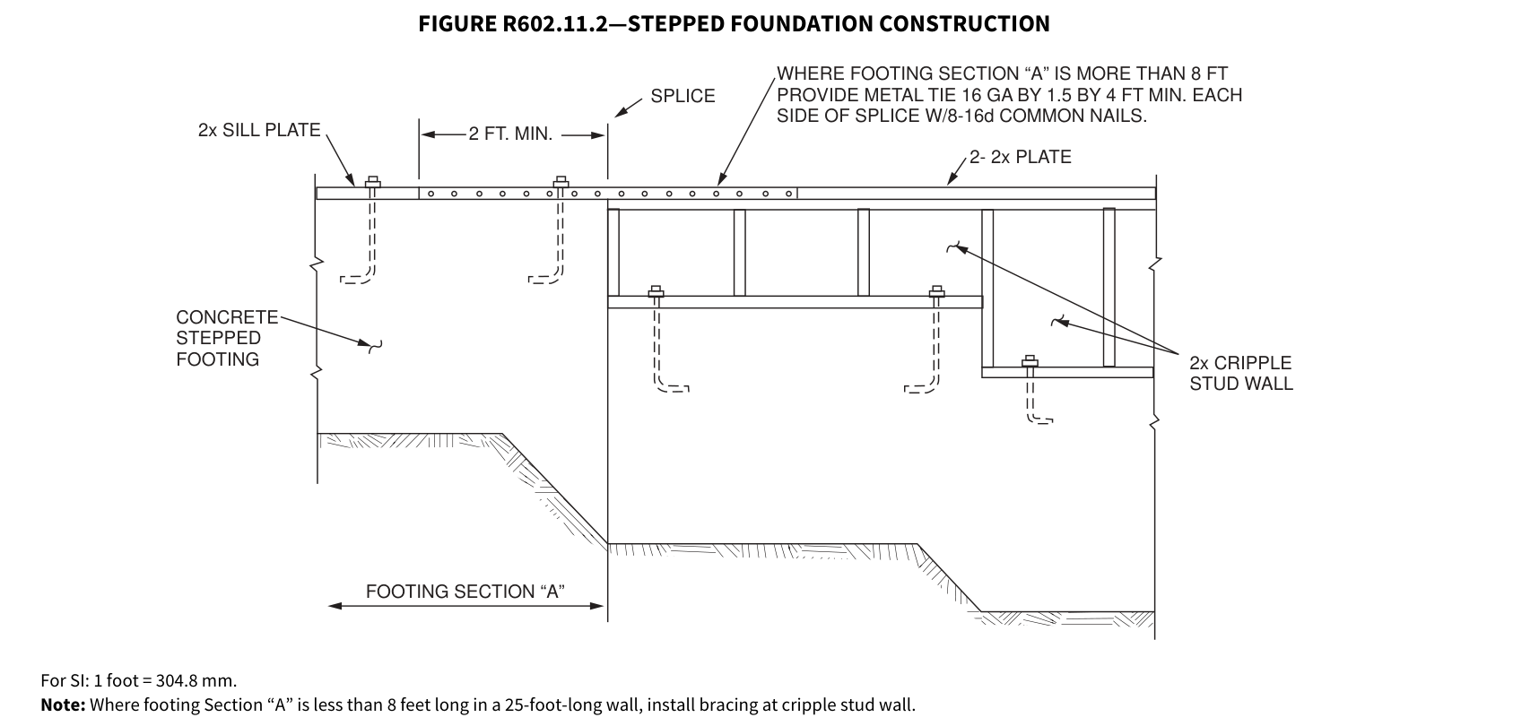 Open full-size illustration ↗
R602.12 Simplified wall bracing.¶
Buildings meeting all of the following conditions shall be permitted to be braced in accordance with this section as an alternative to the requirements of Section R602.10. The entire building shall be braced in accordance with this section; the use of other bracing provisions of Section R602.10, except as specified herein, shall not be permitted.
There shall be not more than three stories above the top of a concrete or masonry foundation or basement wall. Permanent wood foundations shall not be permitted.
Floors shall not cantilever more than 24 inches (607 mm) beyond the foundation or bearing wall below.
Wall height shall not be greater than 10 feet (3048 mm).
The building shall have a roof eave-to-ridge height of 15 feet (4572 mm) or less.
Exterior walls shall have gypsum board with a minimum thickness of 1/2 inch (12.7 mm) installed on the interior side fastened in accordance with Table R702.3.5.
The structure shall be located where the ultimate design wind speed is less than or equal to 130 mph (58 m/s), and the exposure category is B or C.
The structure shall be located in Seismic Design Category A, B or C for detached one- and two-family dwellings or Seismic Design Category A or B for townhouses.
Cripple walls shall not be permitted in three-story buildings.
R602.12.1 Circumscribed rectangle. The bracing required for each building shall be determined by circumscribing a rectangle around the entire building on each floor as shown in Figure R602.12.1. The rectangle shall surround all enclosed offsets and projections such as sunrooms and attached garages. Open structures, such as carports and decks, shall be permitted to be excluded. The rectangle shall not have a side greater than 60 feet (18 288 mm), and the ratio between the long side and short side shall be not greater than 3:1.
FIGURE R602.12.1—RECTANGLE CIRCUMSCRIBING AN ENCLOSED BUILDING
LONG SIDE
TYPICAL SEGMENTS OF TYPICAL SEGMENTS OF WALL BETWEEN CORNERS WALL BETWEEN CORNERS
| LONG SIDE | |
|---|---|
| TYPICAL SEGMENTS OF WALL BETWEEN CORNERS TYPICAL WALL CORNER LONG SIDE CIRCUMSCRIBING RECTANGLE |
|
| SHORT SIDE | SHORT SIDE |
| TYPICAL SEGMENTS OF WALL BETWEEN CORNERS |
|
| CIRCUMSCRIBING RECTANGLE |
FIRST FLOOR PLAN SECOND FLOOR PLAN
R602.12.2 Sheathing materials. The following sheathing materials installed on the exterior side of exterior walls shall be used to construct a bracing unit as defined in Section R602.12.3. Mixing materials is prohibited.
- Wood structural panels with a minimum thickness of 3/8 inch (9.5 mm) fastened in accordance with Table R602.3(3).
- Structural fiberboard sheathing with a minimum thickness of 1/2 inch (12.7 mm) fastened in accordance with Table R602.3(1).
R602.12.3 Bracing unit. A bracing unit shall be a full-height sheathed segment of the exterior wall without openings or vertical or horizontal offsets and a minimum length as specified herein. Interior walls shall not contribute toward the amount of required bracing. Mixing of Items 1 and 2 is prohibited on the same story.
Where all framed portions of all exterior walls are sheathed in accordance with Section R602.12.2, including wall areas between bracing units, above and below openings and on gable end walls, the minimum length of a bracing unit shall be 3 feet (914 mm).
Where the exterior walls are braced with sheathing panels in accordance with Section R602.12.2 and areas between bracing units are covered with other materials, the minimum length of a bracing unit shall be 4 feet (1219 mm).
R602.12.3.1 Multiple bracing units. Segments of wall compliant with Section R602.12.3 and longer than the minimum bracing unit length shall be considered as multiple bracing units. The number of bracing units shall be determined by dividing the wall segment length by the minimum bracing unit length. Full-height sheathed segments of wall narrower than the minimum bracing unit length shall not contribute toward a bracing unit except as specified in Section R602.12.6.
R602.12.4 Number of bracing units. Each side of the circumscribed rectangle, as shown in Figure R602.12.1, shall have, at a minimum, the number of bracing units in accordance with Table R602.12.4 placed on the parallel exterior walls facing the side of the rectangle. Bracing units shall then be placed using the distribution requirements specified in Section R602.12.5.
TABLE R602.12.4—MINIMUM NUMBER OF BRACING UNITS ON EACH SIDE OF THE CIRCUMSCRIBED RECTANGLE
| ** ULTIMATE** DESIGN WIND SPEED (mph) |
** STORY LEVEL** | ** EAVE-TO- RIDGE HEIGHT (feet)** |
** MINIMUM NUMBER OF** BRACING UNITS ON EACH LONG SIDEa, b, d |
** MINIMUM NUMBER OF** BRACING UNITS ON EACH LONG SIDEa, b, d |
** MINIMUM NUMBER OF** BRACING UNITS ON EACH LONG SIDEa, b, d |
** MINIMUM NUMBER OF** BRACING UNITS ON EACH LONG SIDEa, b, d |
** MINIMUM NUMBER OF** BRACING UNITS ON EACH LONG SIDEa, b, d |
** MINIMUM NUMBER OF** BRACING UNITS ON EACH LONG SIDEa, b, d |
** MINIMUM NUMBER OF** BRACING UNITS ON EACH SHORT SIDEa, b, d |
** MINIMUM NUMBER OF** BRACING UNITS ON EACH SHORT SIDEa, b, d |
** MINIMUM NUMBER OF** BRACING UNITS ON EACH SHORT SIDEa, b, d |
** MINIMUM NUMBER OF** BRACING UNITS ON EACH SHORT SIDEa, b, d |
** MINIMUM NUMBER OF** BRACING UNITS ON EACH SHORT SIDEa, b, d |
** MINIMUM NUMBER OF** BRACING UNITS ON EACH SHORT SIDEa, b, d |
|---|---|---|---|---|---|---|---|---|---|---|---|---|---|---|
| ** ULTIMATE** DESIGN WIND SPEED (mph) |
** STORY LEVEL** | ** EAVE-TO- RIDGE HEIGHT (feet)** |
** Length of short side** (feet)c |
** Length of short side** (feet)c |
** Length of short side** (feet)c |
** Length of short side** (feet)c |
** Length of short side** (feet)c |
** Length of short side** (feet)c |
** Length of long side** (feet)c |
** Length of long side** (feet)c |
** Length of long side** (feet)c |
** Length of long side** (feet)c |
** Length of long side** (feet)c |
** Length of long side** (feet)c |
| ** ULTIMATE** DESIGN WIND SPEED (mph) |
** STORY LEVEL** | ** EAVE-TO- RIDGE HEIGHT (feet)** |
** 10** | ** 20** | ** 30** | ** 40** | ** 50** | ** 60** | ** 10** | ** 20** | ** 30** | ** 40** | ** 50** | ** 60** |
| 115 | Top story of a one-, two- or three-story building (original diagram) | 10 | 1 | 2 | 2 | 2 | 3 | 3 | 1 | 2 | 2 | 2 | 3 | 3 |
| 115 | First story of a two-story building or second story of a three-story building (original diagram) | 10 | 2 | 3 | 3 | 4 | 5 | 6 | 2 | 3 | 3 | 4 | 5 | 6 |
| 115 | First story of a three-story building (original diagram) | 10 | 2 | 3 | 4 | 6 | 7 | 8 | 2 | 3 | 4 | 6 | 7 | 8 |
| 115 | Top story of a one-, two- or three-story building (original diagram) | 15 | 1 | 2 | 3 | 3 | 4 | 4 | 1 | 2 | 3 | 3 | 4 | 4 |
| 115 | First story of a two-story building or second story of a three-story building (original diagram) | 15 | 2 | 3 | 4 | 5 | 6 | 7 | 2 | 3 | 4 | 5 | 6 | 7 |
| 115 | First story of a three-story building (original diagram) | 15 | 2 | 4 | 5 | 6 | 7 | 9 | 2 | 4 | 5 | 6 | 7 | 9 |
| 130 | Top story of a one-, two- or three-story building (original diagram) | 10 | 1 | 2 | 2 | 3 | 3 | 4 | 1 | 2 | 2 | 3 | 3 | 4 |
| 130 | First story of a two-story building or second story of a three-story building (original diagram) | 10 | 2 | 3 | 4 | 5 | 6 | 7 | 2 | 3 | 4 | 5 | 6 | 7 |
| 130 | First story of a three-story building (original diagram) | 10 | 2 | 4 | 5 | 7 | 8 | 10 | 2 | 4 | 5 | 7 | 8 | 10 |
| 130 | Top story of a one-, two- or three-story building (original diagram) | 15 | 2 | 3 | 3 | 4 | 4 | 6 | 2 | 3 | 3 | 4 | 4 | 6 |
| 130 | First story of a two-story building or second story of a three-story building (original diagram) | 15 | 3 | 4 | 6 | 7 | 8 | 10 | 3 | 4 | 6 | 7 | 8 | 10 |
| 130 | First story of a three-story building (original diagram) | 15 | 3 | 6 | 7 | 10 | 11 | 13 | 3 | 6 | 7 | 10 | 11 | 13 |
For SI: 1 inch = 25.4 mm, 1 foot = 304.8 mm, 1 mile per hour = 0.447m/s. a. Interpolation shall not be permitted. b. Cripple walls or wood-framed basement walls in a walk-out condition shall be designated as the first story and the stories above shall be redesignated as the second and third stories, respectively, and shall be prohibited in a three-story structure. c. Actual lengths of the sides of the circumscribed rectangle shall be rounded to the next highest unit of 10 when using this table. d. For Exposure Category C, multiply bracing units by a factor of 1.20 for a one-story building, 1.30 for a two-story building and 1.40 for a three-story building.
R602.12.5 Distribution of bracing units. The placement of bracing units on exterior walls shall meet all of the following requirements as shown in Figure R602.12.5.
- A bracing unit shall begin not more than 12 feet (3658 mm) from any wall corner.
- The distance between adjacent edges of bracing units shall be not greater than 20 feet (6096 mm).
- Segments of wall greater than 8 feet (2438 mm) in length shall have not less than one bracing unit.
FIGURE R602.12.5—BRACING UNIT DISTRIBUTION
20 FT. 12 FT. 20 FT.
WALL WALL WALL CORNER CORNER CORNER
4 FT. BRACING UNIT
3 FT. BRACING UNIT
| 20 FT. | 12 FT. | ||
|---|---|---|---|
| MAX | MAX | MAX | |
| 20 FT. | |||
|---|---|---|---|
| MAX | MAX | MAX | |
MULTIPLE BRACING UNITS MULTIPLE BRACING UNITS EQUAL LENGTH DIVIDED BY 4 EQUAL LENGTH DIVIDED BY 3
BRACING WITH AREAS BETWEEN BRACING UNITS WITH ALL FRAMED COVERED WITH OTHER MATERIALS PORTIONS OF WALL SHEATHED
For SI: 1 foot = 304.8 mm.
R602.12.6 Narrow panels. The bracing methods referenced in Section R602.10 and specified in Sections R602.12.6.1 through R602.12.6.3 shall be permitted where using simplified wall bracing.
R602.12.6.1 Method CS-G. Braced wall panels constructed as Method CS-G in accordance with Tables R602.10.4 and R602.10.5 shall be permitted for one-story garages where all framed portions of all exterior walls are sheathed with wood structural panels. Each CS-G panel shall be equivalent to 0.5 of a bracing unit. Segments of wall that include a Method CS-G panel shall meet the requirements of Section R602.10.4.2.
R602.12.6.2 Method CS-PF. Braced wall panels constructed as Method CS-PF in accordance with Section R602.10.6.4 shall be permitted where all framed portions of all exterior walls are sheathed with wood structural panels. Each CS-PF panel shall equal 0.75 bracing units. Segments of wall that include a Method CS-PF panel shall meet the requirements of Section R602.10.4.2.
R602.12.6.3 Methods ABW, PFH and PFG. Braced wall panels constructed as Method ABW, PFH and PFG shall be permitted where bracing units are constructed using wood structural panels applied either continuously or intermittently. Each ABW and PFH panel shall equal one bracing unit and each PFG panel shall be equal to 0.75 bracing unit.
R602.12.7 Lateral support. For bracing units located along the eaves, the vertical distance from the outside edge of the top wall plate to the roof sheathing above shall not exceed 9.25 inches (235 mm) at the location of a bracing unit unless lateral support is provided in accordance with Section R602.10.8.2.
R602.12.8 Stem walls. Masonry stem walls with a height and length of 48 inches (1219 mm) or less supporting a bracing unit or a Method CS-G, CS-PF or PFG braced wall panel shall be constructed in accordance with Figure R602.10.9. Concrete stem walls with a length of 48 inches (1219 mm) or less, greater than 12 inches (305 mm) tall and less than 6 inches (152 mm) thick shall be reinforced sized and located in accordance with Figure R602.10.9.
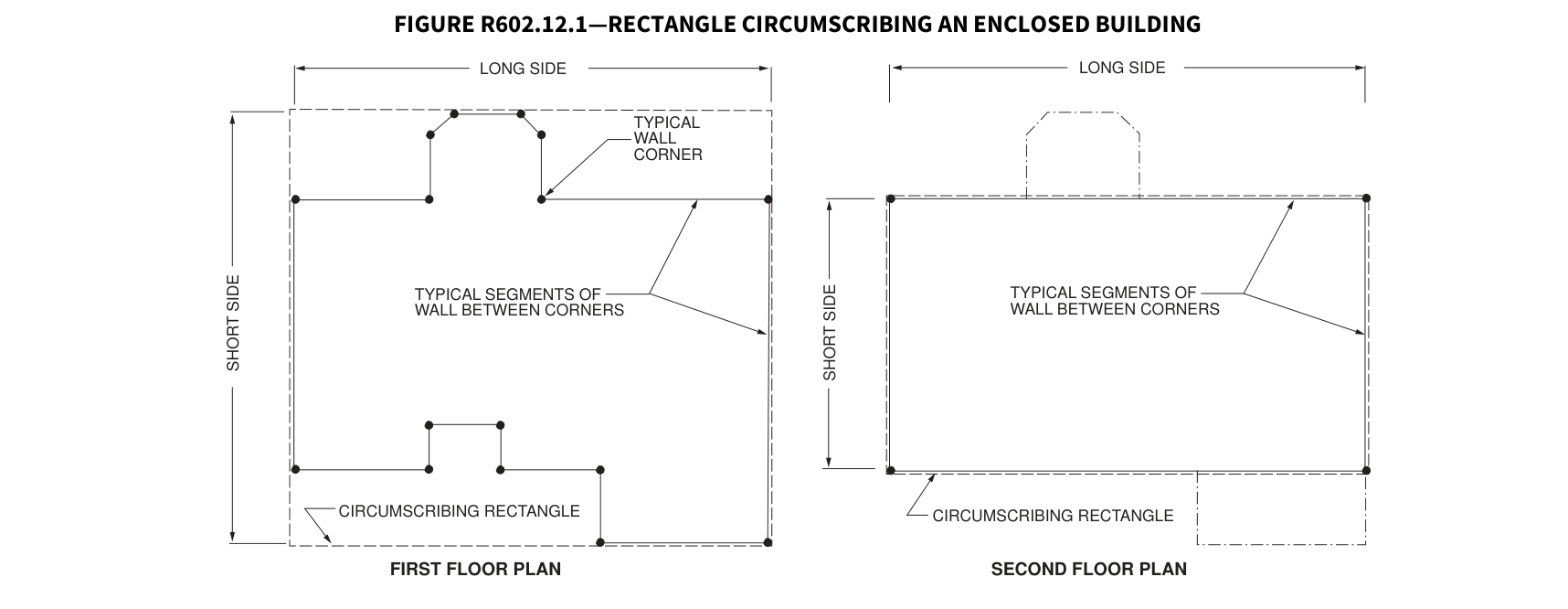 Open full-size illustration ↗
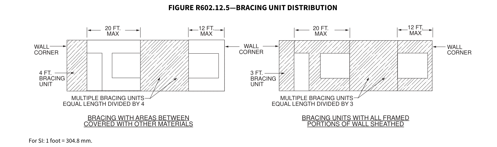 Open full-size illustration ↗
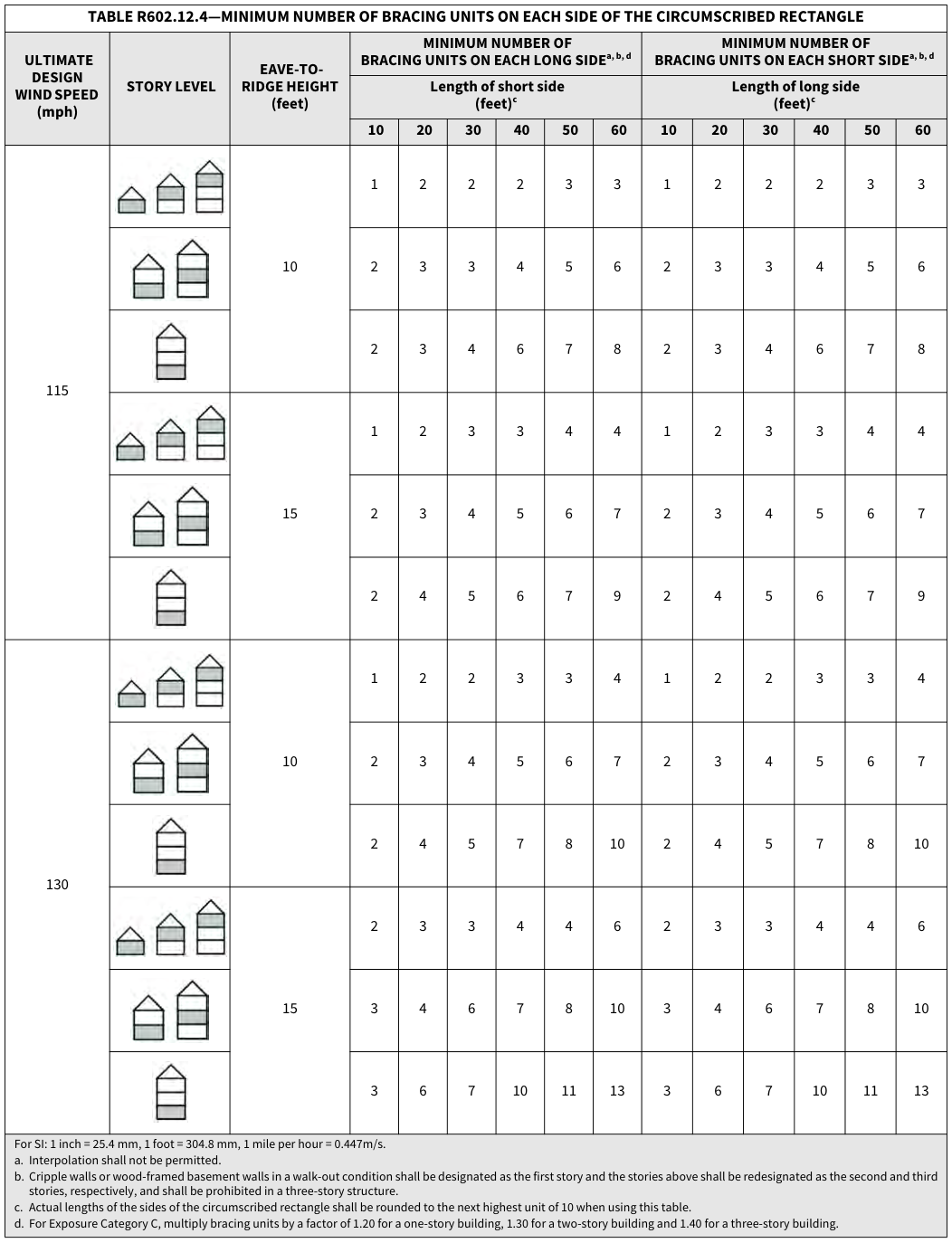 Open full-size table ↗
Explained in plain English
Guides that cite this section.
Get a plain-English answer with a citation back to this text.
Ask AI about this code